5-49
STANDARD AND PTS INTERRUPTS
8. Select PTS service for EPA0.
— Set PTSSEL.2.
9. Set-up EPA0 to capture on both rising and falling edges.
— Set EPA0_CON bits 4 and 5 (Figure 11-10 on page 11-19).
10. Enable the PTS and conventional interrupts.
— Use the EI instruction to enable all standard interrupts and the EPTS instruction to
enable the PTS.
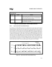
11. Toggle the SCK input to start the reception. Data is shifted into the most-significant
(leftmost) bit first and shifts right with each successive bit received. The EPA generates an
interrupt each time that the SCK input toggles. The PTS receives the next bit of data on the
pin configured as RXD on even PTS cycles. When PTSCOUNT decrements to zero, the
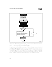
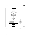
PTS calls the end-of-PTS interrupt (Figure 5-24). The interrupt service routine should
disable the EPA channel, clear the DATA register, reload the PTSCOUNT and PTSCON1
registers, reload EPA0_CON, and select PTS service for EPA0. If the EPA were generating
the SCK signal, the end-of-PTS interrupt service routine would also have to reload the
EPA0_TIME register.
12. To determine when all bytes have been transmitted, create a loop routine to check the
status of the RXDDONE flag.


