8XC196MC, MD, MH USER’S MANUAL
7-8
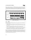
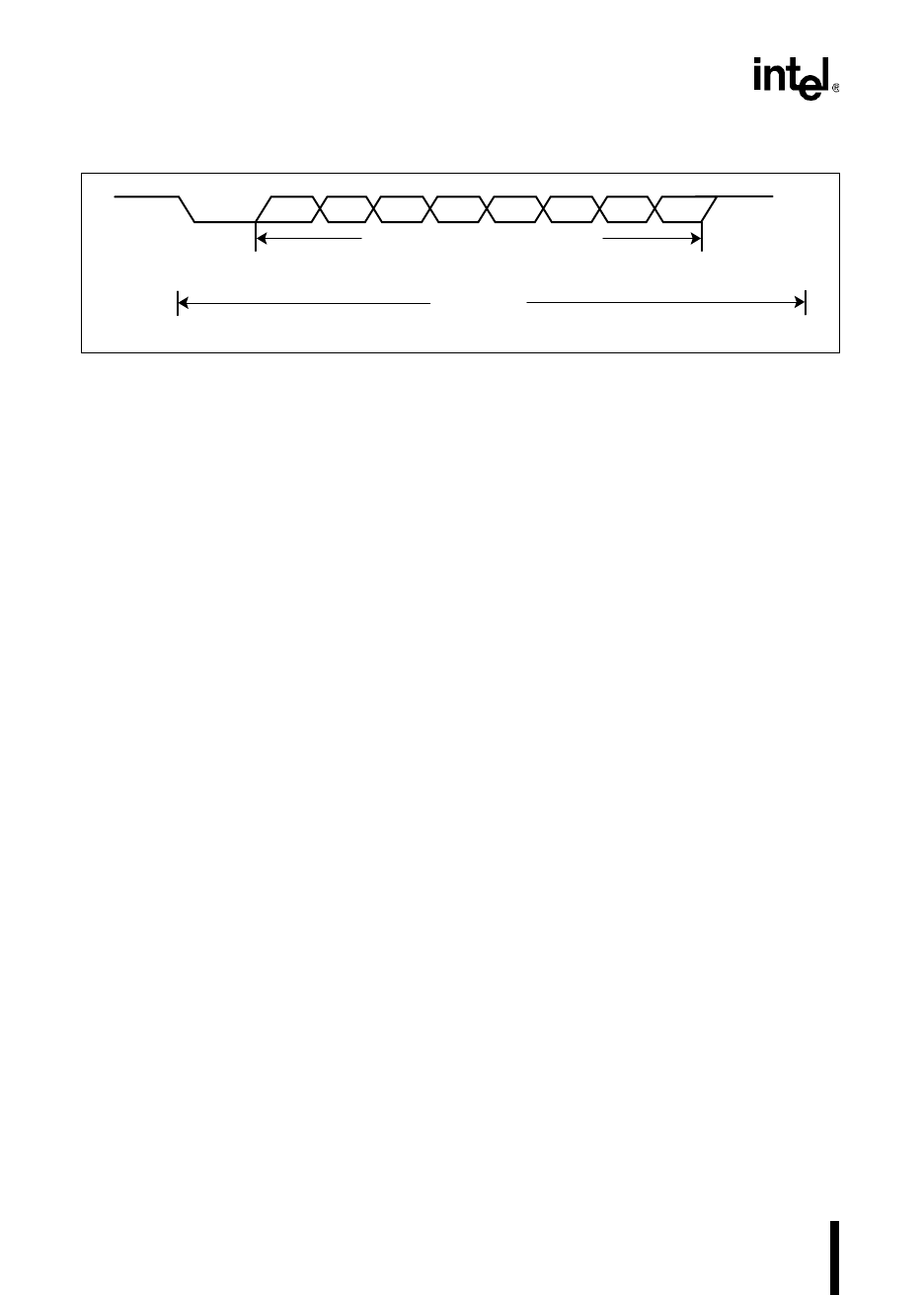
Figure 7-4. Serial Port Frames for Mode 1
The transmit and receive functions are controlled by separate shift clocks. The transmit shift
clock starts when the baud-rate generator is initialized. The receive shift clock is reset when a start
bit (high-to-low transition) is received. Therefore, the transmit clock may not be synchronized
with the receive clock, although both will be at the same frequency.
The transmit interrupt (TI) and receive interrupt (RI) flags in SPx_STATUS are set to indicate
completed operations. During a reception, both the RI flag and the RIx interrupt pending bit are
set just before the end of the stop bit. During a transmission, both the TI flag and the TIx interrupt
pending bit are set at the beginning of the stop bit. The next byte cannot be sent until the stop bit
is sent.
Use caution when connecting more than two devices with the serial port in half-duplex (i.e., with
one wire for transmit and receive). The receiving processor must wait for one bit time after the
RI flag is set before starting to transmit. Otherwise, the transmission could corrupt the stop bit,
causing a problem for other devices listening on the link.
7.3.2.2 Mode 2
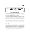
Mode 2 is the asynchronous, ninth-bit recognition mode. This mode is commonly used with mode
3 for multiprocessor communications. Figure 7-5 shows the data frame used in this mode. It con-
sists of a start bit (0), nine data bits (LSB first), and a stop bit (1). During transmissions, setting
the TB8 bit in the SPx_CON register before writing to SBUFx_TX sets the ninth transmission bit.
The hardware clears the TB8 bit after every transmission, so it must be set (if desired) before each
write to SBUFx_TX. During receptions, the RI flag and RIx interrupt pending bit are set only if
the TB8 bit is set. This provides an easy way to have selective reception on a data link. (See “Mul-
tiprocessor Communications” on page 7-9.) Parity cannot be enabled in this mode.
StartStop D0 D1 D2 D3 D4 D5 D6 D7 Stop
8 Bits of Data or 7 Bits of Data
with Parity Bit
10-bit Frame
A0245-02


