8XC196MC, MD, MH USER’S MANUAL
14-10
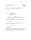
When selecting the capacitor, determine the worst-case discharge time needed for the oscillator
to stabilize, then use this formula to calculate an appropriate value for C
1
.
where:
C
1
is the capacitor value, in farads
T
DIS
is the worst-case discharge time, in seconds
I is the discharge current, in amperes
V
t
is the threshold voltage
NOTE
If powerdown is re-entered and exited before C
1
charges to V
CC
, it will take
less time for the voltage to ramp down to the threshold. Therefore, the device
will take less time to exit powerdown.
For example, assume that the oscillator needs at least 12.5 ms to discharge (T
DIS
= 12.5 ms), V
t
is 2.5 V, and the discharge current is 200 µA. The minimum C
1
capacitor size is 1 µF.
When using an external oscillator, the value of C
1
can be very small, allowing rapid recovery from
powerdown. For example, a 100 pF capacitor discharges in 1.25 µs.
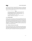
14.5 ONCE MODE
On-circuit emulation (ONCE) mode isolates the device from other components in the system to
allow printed-circuit-board testing or debugging with a clip-on emulator. During ONCE mode,
all pins except XTAL1, XTAL2, V
SS
, and, V
CC
are weakly pulled high or low. During ONCE
mode, RESET# must be held high or the device will exit ONCE mode and enter the reset state.
C
1
T
DIS
I×
V
t
--------------------
=
C
1
0.0125()0.0002()
2.5
--------------------------------------------------
1 µF==
T
DIS
C
1
V
t
×
I
------------------
1.0 10
10–
×()2.5()
0.0002
---------------------------------------------------
1.25 µs== =


