


8XC196MC, MD, MH USER’S MANUAL
5-52
5. Initialize and enable the timer; select up counting, internal clock, and prescaler disabled.
— Set T1CONTROL bits 6 and 7 (Figure 11-8 on page 11-16).
6. Initialize the PTSCB as shown in Table 5-15.
7. Enable EPA0 interrupt.
— Set INT_MASK.2.
8. Load the number of bytes to transmit into the user_defined transmit count register
(T_COUNT) and clear the user-defined transfer-done flag (TXDDONE).
— LD T_COUNT, #16
— CLRB TXDDONE
9. Select PTS service for EPA0.
— Set PTSSEL.2.
10. Set-up the transmission start bit.
— Clear P2.0.
11. Set-up EPA0 as a compare-only channel.
— Set EPA0_CON.6 (Figure 11-10 on page 11-19).
12. Start the operation of the EPA0 channel by writing the time of the first interrupt to
EPA0_TIME. To set-up the correct value, add the baud_value (1A0H) to the current
TIMER1 value and store the result in EPA0_TIME. The baud_value determines the time
to the first PTS interrupt. When the interrupt occurs, the PTS transmits the first data bit.
The baud_value of 1A0H selects a baud rate of 9600.
13. Enable the PTS and conventional interrupts.
— Use the EI instruction to enable all standard interrupts and the EPTS instruction to
enable the PTS.
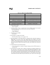
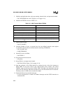
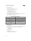
Table 5-15. ASIO Transmit Mode PTSCBs
PTSCB1 PTSCB2
PTSVEC (H) = pointer to PTSCB2 Unused
PTSVEC (L) = pointer to PTSCB2 SAMPTIME = unused
BAUD (H) = 01H (9600 baud at 16 MHz) DATA (H) = unused
BAUD (L) = A0H (9600 baud at 16 MHz) DATA (L) =
nn
H (8 data bits)
EPAREG (H) = 1FH (EPA0_TIME) PTSCON1 = 21H (enable odd parity)
EPAREG (L) = 42H (EPA0_TIME) PORTMASK = 01H (P2.0 = TXD)
PTSCON = 60H (ASIO transmit mode) PORTREG (H) = 1FH (P2_REG)
PTSCOUNT = 0AH (8 data bits, 1 parity, & 1 stop
bit)
PORTREG (L) = D4H (P2_REG)