8XC196MC, MD, MH USER’S MANUAL
10-4
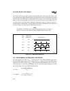
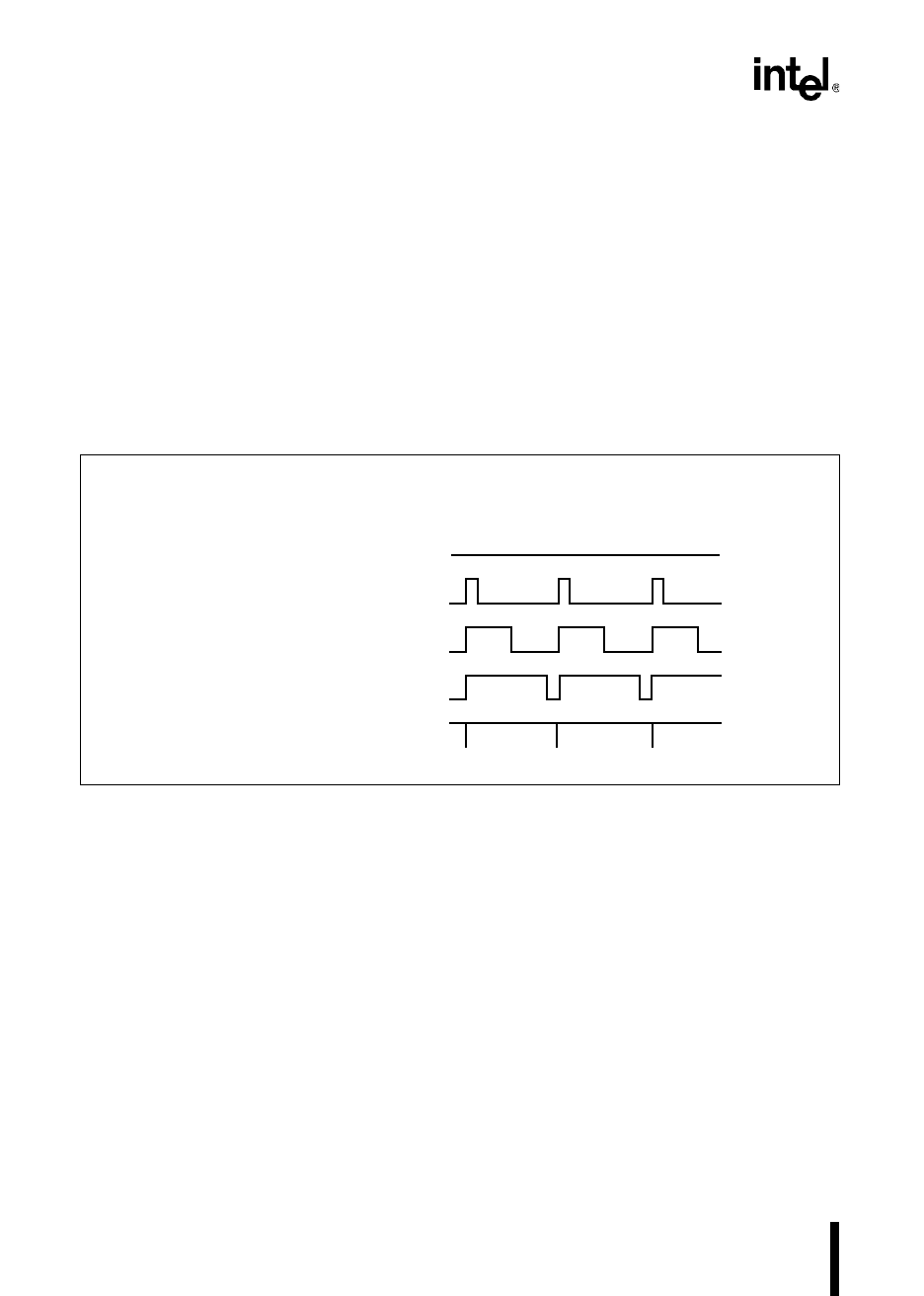
The counter counts down to 00H, at which time the PWM output is driven high, the counter value
is reloaded from the PWM_PERIOD register, and the contents of the control registers are loaded
into the buffers. The PWM output remains high until the counter value matches the value in the
buffer, at which time the output is pulled low. You can read the count register (PWM_COUNT)
to see the current value of the counter. When the counter resets again (i.e., when an overflow oc-
curs) the output is switched high. (Loading PWMx_CONTROL with 00H forces the output to re-
main low.) Figure 10-2 shows typical PWM output waveforms.
NOTE
The PWMx_CONTROL register value and corresponding duty cycle result, in
Figure 10-2, are true only when the PWM_PERIOD register value is FFH.
Figure 10-2. PWM Output Waveforms
10.4 PROGRAMMING THE FREQUENCY AND PERIOD
The input frequency on XTAL1 (F
XTAL
1
) and the contents of the PWM_PERIOD register deter-
mine the PWM output frequency (F
PWM
) and period (T
PWM
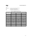
). Table 10-3 shows the PWM output
frequencies for common values of F
XTAL
1
with a variety of PWM_PERIOD values. Use the fol-
lowing formulas to calculate the PWM period value for the desired output frequency and write
the corresponding value to the PWM_PERIOD register.
T
PWM
(in µs) =
F
PWM
(in MHz) =
Duty
Cycle
0
0
0
0
0
PWM Control
Register Value
0% 00H
10% 19H
50% 80H
90% E6H
99.6% FFH
Output Waveform
A0119-02
512 (PWM_PERIOD 1)+×
F
XTAL1
----------------------------------------------------------------------------
F
XTAL1
512 (× PWM_PERIOD 1)+
----------------------------------------------------------------------------


