7-5
SERIAL I/O (SIO) PORT
7.3.1 Synchronous Modes (Modes 0 and 4)
The 8XC196MH serial port has two synchronous modes, mode 0 and mode 4. Mode 0 is the syn-
chronous mode available on all the 8XC196 devices that have serial ports. Mode 4 is an enhanced,
full-duplex synchronous mode.
7.3.1.1 Mode 0
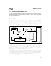
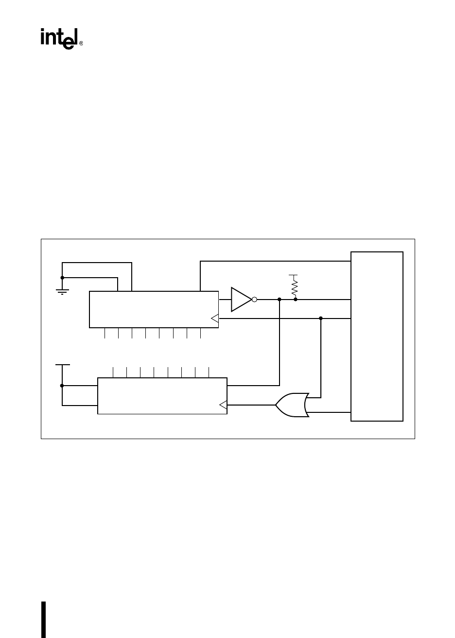
The most common use of mode 0 is to expand the I/O capability of the device with shift registers
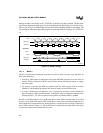
(see Figure 7-2). In this mode, the TXDx pin outputs a set of eight clock pulses, while the RXDx
pin either transmits or receives data. Data is transferred eight bits at a time with the least-signif-
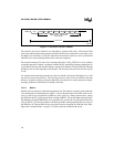
icant bit first. Figure 7-3 shows a diagram of the relative timing of these signals. Note that only
mode 0 uses RXDx as an open-drain output.
Figure 7-2. Typical Shift Register Circuit for Mode 0
In mode 0, RXDx must be enabled for receptions and disabled for transmissions. (See “Program-
ming the Control Register” on page 7-10.) When RXDx is enabled, either a rising edge on the
RXDx input or clearing the receive interrupt (RI) flag in SPx_STATUS starts a reception. When
RXDx is disabled, writing to SBUFx_TX starts a transmission.
Disabling RXDx stops a reception in progress and inhibits further receptions. To avoid a partial
or undesired complete reception, disable RXDx before clearing the RI flag in SPx_STATUS. This
can be handled in an interrupt environment by using software flags or in straight-line code by us-
ing the interrupt pending register to signal the completion of a reception.
Clock Inhibit
Serial In
Shift / LOAD#
P
x
.
x
RXD
TXD
Microcontroller
Shift Register
74HC165
Shift Register
74HC164
Inputs
Outputs
Serial
In B
Clear
P
x
.
x
Clock
Serial In A
V
CC
Enable#
Clock
Data
15kΩ
74HC05
Q#
A0264-03
V
CC


