8XC196MC, MD, MH USER’S MANUAL
9-4
9.3 WAVEFORM GENERATOR OPERATION
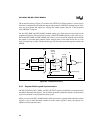
This section describes the major components of the waveform generator: the timebase generator,
the phase driver channels, and the control and protection circuitry. It also explains how the buff-
ered registers are updated and describes the similarities and differences between the center-
aligned and edge-aligned operating modes. Finally, it describes the two types of interrupt requests
that the waveform generator can generate and explains how to enable the interrupts.
9.3.1 Timebase Generator
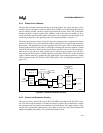
The timebase generator establishes the carrier period of the PWM outputs. You specify this period
by writing a value to the reload register (WG_RELOAD). This value is loaded into the counter
register (WG_COUNTER) when the system is initialized and periodically (depending on the op-
erating mode) thereafter. You can read the counter register to determine the current counter value
and you can write to the reload register to change the reload value at any time.
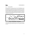
The 16-bit timebase counter is clocked every state time. The control register (WG_CONTROL)
enables and disables the counter, controls the counting mode, and reflects the count direction.
When the counter is enabled, it continuously counts between 0001H and the reload value. Writing
0000H to the reload register or clearing the enable bit in the control register stops the counter.
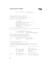
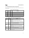
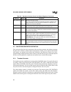
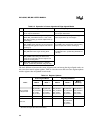
WG_CONTROL 1FCCH Waveform Generator Control
The control register determines the waveform generator’s operating mode,
starts and stops the counter, specifies the dead time for all phases, and
indicates the current count direction.
WG_COUNTER 1FCAH Waveform Generator Count Value
The read-only counter register reflects the current counter value.
WG_OUTPUT 1FC0H Waveform Generator Output Control
The output control register configures the waveform generator’s outputs and
selects their active polarity.
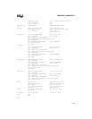
WG_PROTECT 1FCEH Waveform Generator Protection
The protection register enables and disables the protection circuitry and the
outputs, selects level-sensitive or edge-triggered interrupts, and controls
which value of the edge or level will trigger an interrupt request.
8XC196MH only: This register also selects the method for disabling the
outputs: inactive states or weak pull-ups.
WG_RELOAD 1FC8H Waveform Generator Reload Value
The reload register contains a value that is compared with the counter value.
The actions performed based on this comparison depend on the operating
mode.
Table 9-2. Waveform Generator Control and Status Registers (Continued)
Mnemonic Address Description


