


8XC196MC, MD, MH USER’S MANUAL
2-8
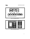
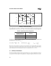
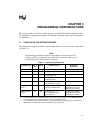
Figure 2-4. Internal Clock Phases
The combined period of phase 1 and phase 2 of the internal CLKOUT signal defines the basic
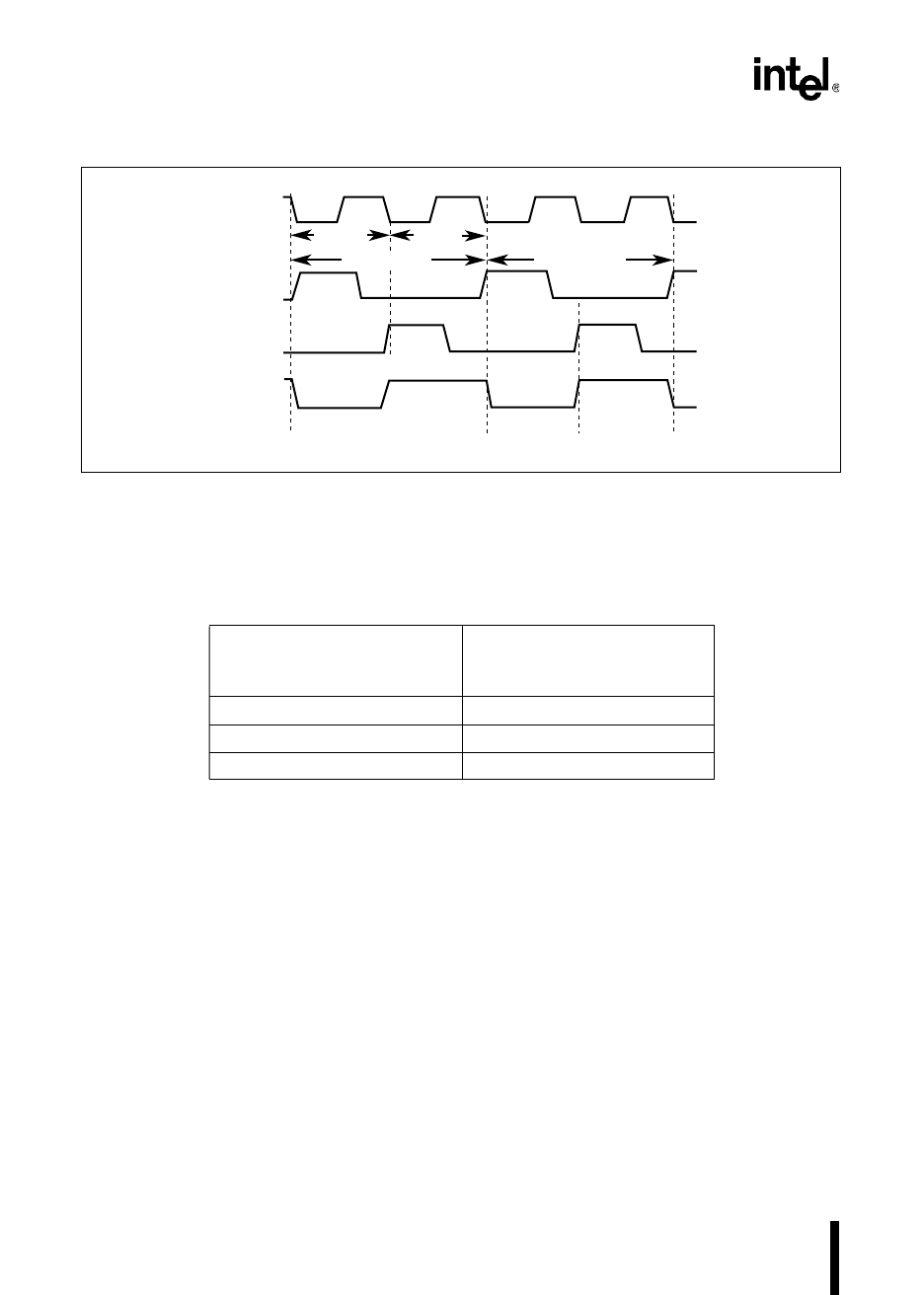
time unit known as a state time or state. Table 2-2 lists state time durations at various frequencies.
The following formulas calculate the frequency of PH1 and PH2, the duration of a state time, and
the duration of a clock period (T
XTAL1
).
Because the microcontroller can operate at many frequencies, this manual defines time require-
ments (such as instruction execution times) in terms of state times rather than specific measure-
ments. Datasheets list AC characteristics in terms of clock periods (T
XTAL1
or T
OSC
).
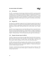
2.5 INTERNAL PERIPHERALS
The internal peripheral modules provide special functions for a variety of applications. This sec-
tion provides a brief description of the peripherals; subsequent chapters describe them in detail.
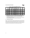
Table 2-2. State Times at Various Frequencies
F
XTAL1
(Frequency Input to the
Divide-by-two Circuit)
State Time
8 MHz 250 ns
12 MHz 167 ns
16 MHz 125 ns
PH1
PH2
CLKOUT
Phase 1 Phase 2
XTAL1
A0114-04
1 State Time
Phase 1 Phase 2
T
XTAL1
1 State Time
T
XTAL1
PH1 (in MHz)
F
XTAL1
2
-------------------
PH2== State Time (in µs)
2
F
XTAL1
-------------------
= T
XTAL1
1
F
XTAL1
-------------------
=