15-17
INTERFACING WITH EXTERNAL MEMORY
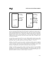
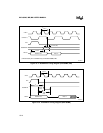
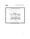
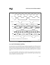
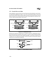
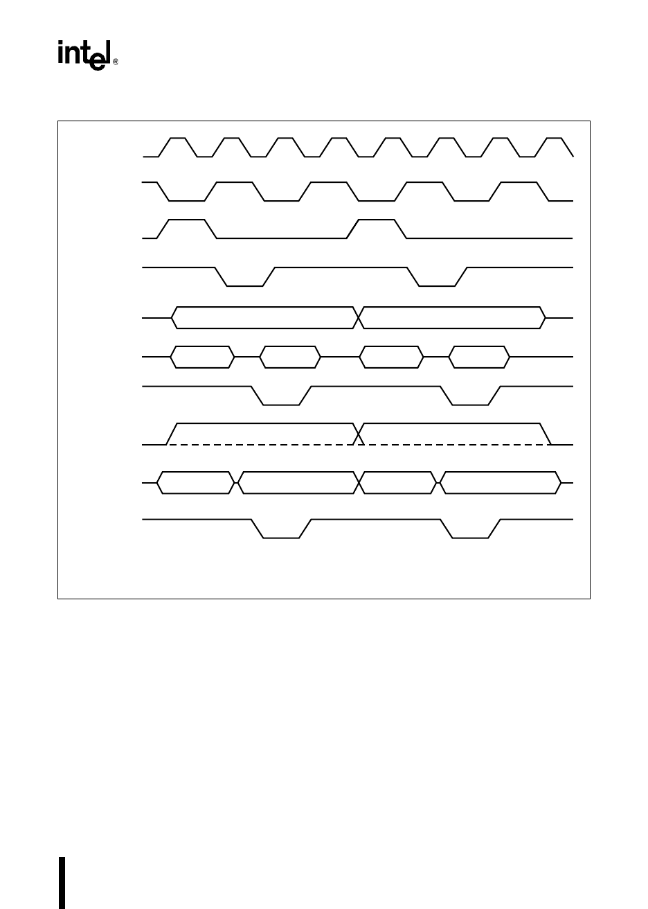
Figure 15-7. Timings for 8-bit Buses
15.4 WAIT STATES (READY CONTROL)
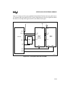
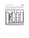
An external device can use the READY input to lengthen an external bus cycle. When an external
address is placed on the bus, the external device can pull the READY signal low to indicate it is
not ready. In response, the microcontroller inserts wait states to lengthen the bus cycle until the
external device raises the READY signal. Each wait state adds one state time (2T
XTAL1
) to the bus
cycle.
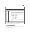
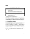
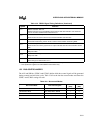
After reset and until CCB1 is fetched, the bus controller always inserts three wait states into bus
cycles. Then, until P5.6 has been configured to operate as the READY signal, the internal ready
control bits (IRC2:0) control the wait states.
CLKOUT
†
ALE
BUSWIDTH
AD15:8
RD#
INST
AD7:0
(write)
WR#
Address
Out
Address Out
Low data in
Address
Out
Low data out
AD7:0
(read)
XTAL1
Address
+1 Out
High data out
High data in
Address Out
Address
+1 Out
A3164-01
† The CLKOUT pin is available only on the 8XC196MC, MD.


