9-19
WAVEFORM GENERATOR
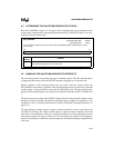
9.5 DETERMINING THE WAVEFORM GENERATOR’S STATUS
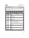
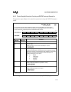
Read WG_CONTROL (Figure 9-12 on page 9-18) to determine the current dead-time value,
counter status, count direction, and operating mode. Read WG_COUNTER (Figure 9-13) to de-
termine the current counter value.
9.6 ENABLING THE WAVEFORM GENERATOR INTERRUPTS
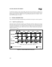
The waveform generator can generate two types of interrupt requests. The WG interrupt request
is triggered by the counter, while the EXTINT interrupt is triggered by an external event.
Mode 0 generates a WG interrupt request once per period, when the counter reaches the
WG_RELOAD value. Mode 1 generates a WG interrupt request twice per period, first when the
counter reaches 1 and again when it reaches the WG_RELOAD value. The edge-aligned modes
generate a WG interrupt request once at the end of each period, when the counter is reloaded with
1.
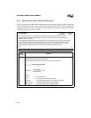
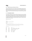
The protection circuitry controls the EXTINT interrupt. Two bits in the protection register control
the type of external event that will generate an interrupt request: a falling or rising edge or a low
or high level. (See “Controlling the Protection Circuitry and EXTINT Interrupt Generation” on
page 9-15.)
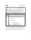
The edge detection circuitry requires a signal to remain asserted for at least 2 state times to be
considered a valid edge. The sample circuitry requires a signal to remain asserted for at least 24
state times to be considered a valid level. It samples the input level 3 times during this 24-state
period and recognizes the signal as valid only if it is asserted for each sample. Level sampling is
useful for environments in which noise spikes might cause unintended interrupts if edge detection
were used.
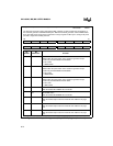
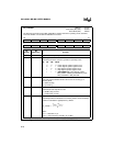
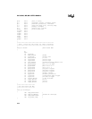
WG_COUNTER
Address:
Reset State (MC, MD):
Reset State (MH):
1FCAH
XXXXH
0000H
You can read the waveform generator counter (WG_COUNTER) register to determine the current
counter value.
15 0
Counter Value
Bit
Number
Function
15:0 Counter Value
This register reflects the current counter value.
Figure 9-13. Waveform Generator Counter (WG_COUNTER) Register


