


15-33
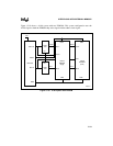
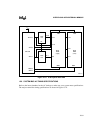
INTERFACING WITH EXTERNAL MEMORY
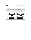
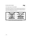
15.6.1 Explanation of AC Symbols
Each symbol consists of two pairs of letters prefixed by “T” (for time). The characters in a pair
indicate a signal and its condition, respectively. Symbols represent the time between the two sig-
nal/condition points. For example, T
LLRL
is the time between signal L (ALE/ADV#) condition L
(Low), and signal R (RD#) condition L (Low). Table 15-7 defines the signal and condition codes.
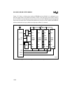
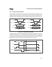
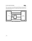
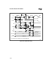
15.6.2 AC Timing Definitions
Tables 15-8 and 15-9 define the AC timing specifications that the memory system must meet and
those that the microcontroller will provide.
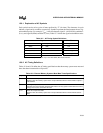
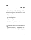
Table 15-7. AC Timing Symbol Definitions
Signals Conditions
A Address Q Output Data H High
B BHE# R RD# L Low
C
†
CLKOUT W WR#, WRH#, WRL# V Valid
D Input Data X XTAL1 X No Longer Valid
G BUSWIDTH Y READY Z Floating
L ALE/ADV#
†
The CLKOUT pin is available only on the 8XC196MC, MD microcontrollers.
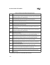
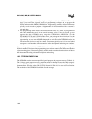
Table 15-8. External Memory Systems Must Meet These Specifications
Symbol Definition
T
AVDV
Address Valid to Input Data Valid
Maximum time the memory system has to output valid data after the microcontroller outputs a
valid address.
T
RHDZ
RD# High to Input Data Float
Time after the microcontroller deasserts RD# until the memory system must float the bus. If this
timing is not met, bus contention will occur.
T
RLDV
RD# Low to Input Data Valid
Maximum time the memory system has to output valid data after th
e
microcontroller asserts
RD#.
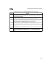
†
The CLKOUT pin is available only on the 8XC196MC, MD microcontrollers.