13-9
MINIMUM HARDWARE CONSIDERATIONS
The 8XC196MH provides the option of an internal-only reset or an internal reset that is also re-
flected externally (by the RESET# pin). The GEN_CON register controls whether an internal re-
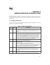
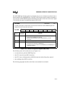
set asserts the external RESET# signal and indicates the source of the most recent reset. Figure
13-8 describes the general configuration register, GEN_CON.
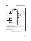
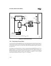
The following events will reset the device (see Figure 13-9):
• an external device pulls the RESET# pin low
• the CPU issues the reset (RST) instruction
• the CPU issues an idle/powerdown (IDLPD) instruction with an illegal key operand
• the watchdog timer (WDT) overflows
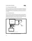
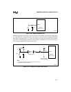
The following paragraphs describe each of these reset methods in more detail.
GEN_CON
(8XC196MH)
Address:
Reset State:
1FA0H
00H
The GEN_CON register controls whether an internal reset asserts the external RESET# signal and
indicates the source of the most recent reset.
7 0
8XC196MH
RSTS — — — — — — DR0
Bit
Number
Bit
Mnemonic
Function
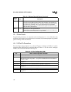
7 RSTS Reset source (read-only status bit)
0 = external reset (RESET# pin asserted)
1 = internal reset (watchdog overflow, illegal IDLPD key, or RST
instruction)
6:1 — Reserved; for compatibility with future devices, write zeros to these bits.
0 DRO Disable RESET# out
0 = an internal reset asserts the RESET# pin.
1 = an internal reset has no effect on the RESET# pin; the RESET# pin is
pulled high (inactive).
Figure 13-8. General Configuration Register (GEN_CON)


