


6-11
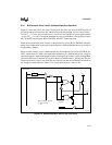
I/O PORTS
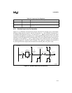
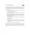
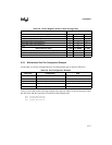
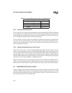
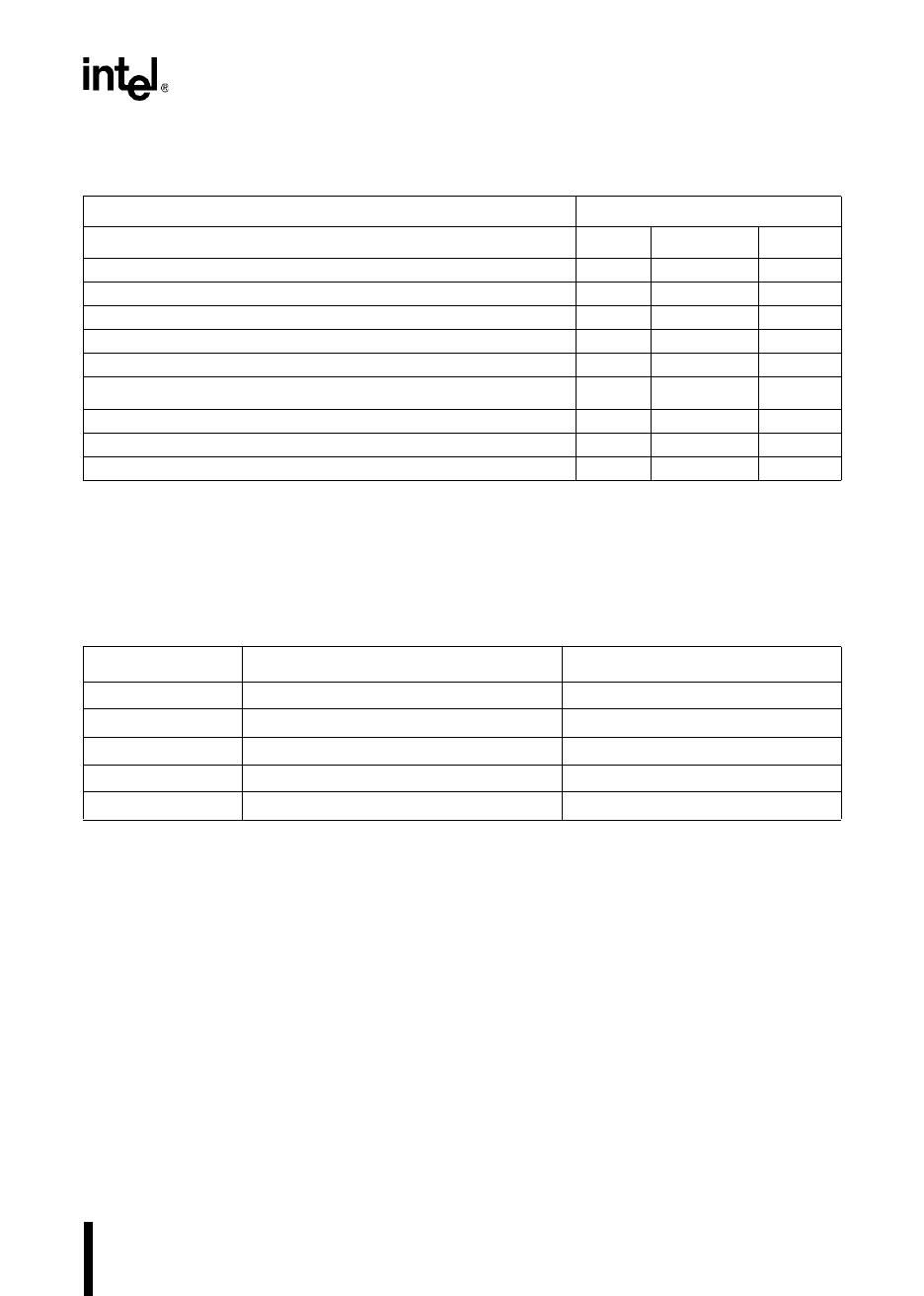
6.3.3 Bidirectional Port Pin Configuration Example
Assume that you wish to configure the pins of a bidirectional port as shown in Table 6-9.
To do so, you could use the following example code segment. Table 6-10 shows the state of each
pin after reset and after execution of each line of the example code.
LDB P
x
_DIR,#00011111B
LDB P
x
_MODE,#00000000B
LDB P
x
_REG,#10010011B
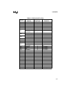
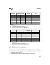
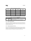
Table 6-8. Control Register Values for Each Configuration
Desired Pin Configuration Configuration Register Settings
Standard I/O Signal P
x
_DIR P
x
_MODE
†
P
x
_REG
Complementary output, driving 0 0 0 0
Complementary output, driving 1 0 0 1
Open-drain output, strongly driving 0 1 0 0
Open-drain output, high impedance 1 0 1
Input 1 0 1
Special-function signal P
x
_DIR P
x
_MODE
†
P
x
_REG
Complementary output, output value controlled by peripheral 0 1 X
Open-drain output, output value controlled by peripheral 1 1 X
Input 1 1 1
†
During reset and until the first write to P
x
_MODE, the pins are weakly held high.
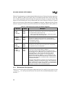
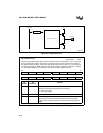
Table 6-9. Port Configuration Example
Port Pin(s) Configuration Data
P
x
.0, P
x
.1 high-impedance input high impedance
P
x
.2, P
x
.3 open-drain output 0
P
x
.4 open-drain output 1 (assuming external pull-up)
P
x
.5, P
x
.6 complementary output 0
P
x
.7 complementary output 1