


5-15
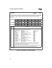
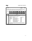
STANDARD AND PTS INTERRUPTS
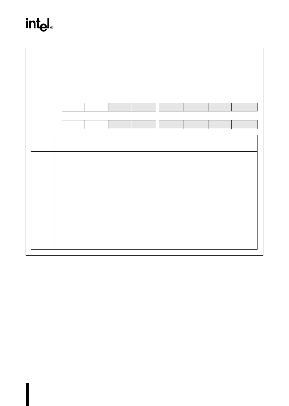
INT_MASK
Address:
Reset State:
0008H
00H
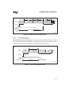
The interrupt mask (INT_MASK) register enables or disables (masks) individual interrupt requests.
(The EI and DI instructions enable and disable servicing of all maskable interrupts.) INT_MASK is the
low byte of the processor status word (PSW). PUSHF or PUSHA saves the contents of this register
onto the stack and then clears this register. Interrupt calls cannot occur immediately following this
instruction. POPF or POPA restores it.
7 0
MC, MD COMP2 EPA2
COMP1 EPA1 COMP0 EPA0 AD OVRTM
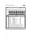
7 0
MH COMP3 COMP2
COMP1 EPA1 COMP0 EPA0 AD OVRTM
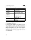
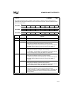
Bit
Number
Function
7:0 Setting a bit enables the corresponding interrupt.
The standard interrupt vector locations are as follows:
Bit Mnemonic Interrupt Standard Vector
COMP2 (MC, MD) EPA Compare-only Channel 2 200EH
COMP3 (MH) EPA Compare-only Channel 3 200EH
EPA2 (MC, MD) EPA Capture/Compare Channel 2 200CH
COMP2 (MH) EPA Compare Channel 2 200EH
COMP1 EPA Compare Channel 1 200AH
EPA1 EPA Capture/Compare Channel 1 2008H
COMP0 EPA Compare Channel 0 2006H
EPA0 EPA Capture/Compare Channel 0 2004H
AD A/D Conversion Complete 2002H
OVRTM
†
Overflow/Underflow Timer 2000H
†
Both timer 1 and timer 2 can generate the multiplexed overflow/underflow interrupt. Write
to PI_MASK to enable the interrupt sources; read PI_PEND to determine which source
caused the interrupt.
Figure 5-7. Interrupt Mask (INT_MASK) Register