


8XC196MC, MD, MH USER’S MANUAL
11-2
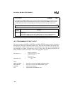
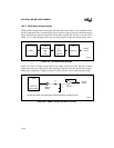
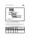
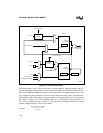
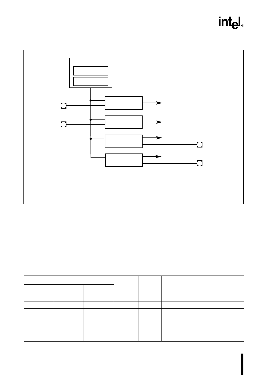
Figure 11-1. EPA Block Diagram
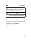
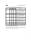
11.2 EPA AND TIMER/COUNTER SIGNALS AND REGISTERS
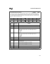
Table 11-2 describes the EPA and timer/counter input and output signals. Each signal is multi-
plexed with a port pin as shown in the first column. Table 11-3 briefly describes the registers for
the EPA capture/compare channels, EPA compare-only channels, and timer/counters.
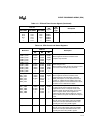
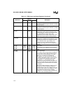
Table 11-2. EPA and Timer/Counter Signals
Port Pin
EPA
Signals
EPA
Signal
Type
Description
8XC196MC 8XC196MD 8XC196MH
P1.2 P1.2 P0.6 T1CLK I External clock source for timer 1.
P1.3 P1.3 P0.7 T1DIR I External direction control for timer 1.
P2.0
P2.1
P2.2
P2.3
—
—
P2.0
P2.1
P2.2
P2.3
P7.0
P7.1
P2.0
P2.2
—
—
—
—
EPA0
EPA1
EPA2
EPA3
EPA4
EPA5
I/O High-speed input/output for the
capture/compare channels.
A2846-01
TIMER1
TIMER2
Timer-counter Unit
Compare-only
Channel
y
Compare-only
Channel 0
Capture/Compare
Channel
x
Capture/Compare
Channel 0
COMP
y
COMP0
EPA
x
EPA0
EPA0 Interrupt
EPA
x
Interrupt
COMP0 Interrupt
COMP
y
Interrupt
.
.
.
.
.
.
Notes:
For the 8XC196MC,
x
&
y
= 3.
For the 8XC196MD,
x
&
y
= 5.
For the 8XC196MH,
x
= 1 &
y
= 3.