13-13
MINIMUM HARDWARE CONSIDERATIONS
You must write two consecutive bytes to the watchdog register (location 0AH) to clear it. For the
8XC196MC and MD, the first byte must be 1EH and the second must be E1H. For the
8XC196MH, the first byte must also be 1EH; however, the second byte can be one of four values.
The second byte determines the reset interval (Table 13-3). Only the values listed in the table are
valid; an invalid value will not clear the register, so the counter will overflow and the watchdog
will reset the device. We recommend that you disable interrupts before writing to the watchdog
register. If an interrupt occurs between the two writes, the watchdog register will not be cleared.
NOTE (8XC196MH Only)
If the WDE bit of CCR1 is cleared, the watchdog is activated immediately
after a system power-up or a device reset. You must clear the watchdog register
within 64K state times after a system power-up or a device reset. At that time,
you can choose a longer interval for subsequent watchdog resets.
If enabled, the watchdog continues to run in idle mode. The device must be awakened before the
end of the reset interval to clear the watchdog; otherwise, the watchdog will reset the device,
which causes it to exit idle mode.
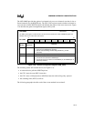
Table 13-3. Selecting the Watchdog Reset Interval (8XC196MH only)
First Byte Second Byte Reset Interval
1EH E1H 64K states
1EH A1H 128K states (2 × 64K)
1EH 61H 256K states (4 × 64K)
1EH 21H 512K states (8 × 64K)


