16-25
PROGRAMMING THE NONVOLATILE MEMORY
16.9 AUTO PROGRAMMING MODE
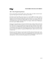
The auto programming mode is a low-cost programming alternative. Using this programming
mode, the device programs itself with data from an external EPROM (external locations 4000H
and above; see Table 16-1 on page 16-3). A bank switching mechanism provided by port 1 pins
(see Figure 16-12) supports auto programming of devices with more than 16 Kbytes of internal
memory.
16.9.1 Auto Programming Circuit and Memory Map
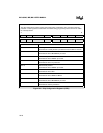
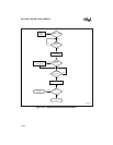
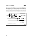
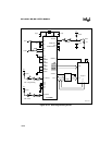
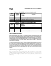
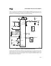
Figure 16-12 shows the recommended circuit for auto programming mode. Table 16-11 shows the
8XC196MC/MD memory map and Table 16-11 shows the 8XC196MH auto programming mem-
ory map. Auto programming is specified for a crystal frequency of 6 to 8 MHz. At 8 MHz, use a
27(C)512 EPROM with tACC = 250 ns and tOE = 100 ns or faster specifications.
Tie the BUSWIDTH pin low to configure an 8-bit data bus. Connect P1.3:0 (8XC196MH only)
as shown to generate the high-order bits of the external EPROM address. Connect P0.7:4 to V
SS
and V
CC
to select auto programming (1100B = 0CH). PACT# and PVER are status outputs, buff-
ered by the 74HC14s. They drive LEDs that indicate programming active (PACT#) and program-
ming verification (PVER). Connect all unused inputs to ground (V
SS
) and leave unused outputs
floating. READY and NMI are active; connect them as indicated.
NOTE
All external EPROM addresses specified in this section are given for the
circuit in Figure 16-12. If you choose a different circuit, you must adjust the
addresses accordingly.
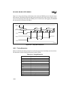
T
PHPL
PROG# High to Next PROG# Low.
T
PHIL
PROG# High to AINC# Low.
T
ILIH
AINC# Pulse Width.
T
ILVH
PVER Hold After AINC# Low.
T
ILPL
AINC# Low to PROG# Low.
T
PHVL
PROG# High to PVER Valid.
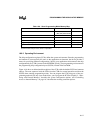
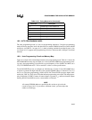
Table 16-10. Timing Mnemonics (Continued)
Mnemonic Description


