


4
SETUP AND PROCEDURES BEFORE OPERATION
4.4 Wiring
4.4.2 External wiring
4 - 9
1
OVERVIEW
2
SYSTEM
CONFIGURATION
3
SPECIFICATIONS
4
SETUP AND
PROCEDURES BEFORE
OPERATION
5
UTILITY PACKAGE (GX
CONFIGURATOR-TI)
6
PROGRAMMING
7
ONLINE MODULE
CHANGE
8
TROUBLESHOOTING
POINT
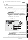
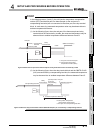
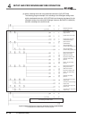
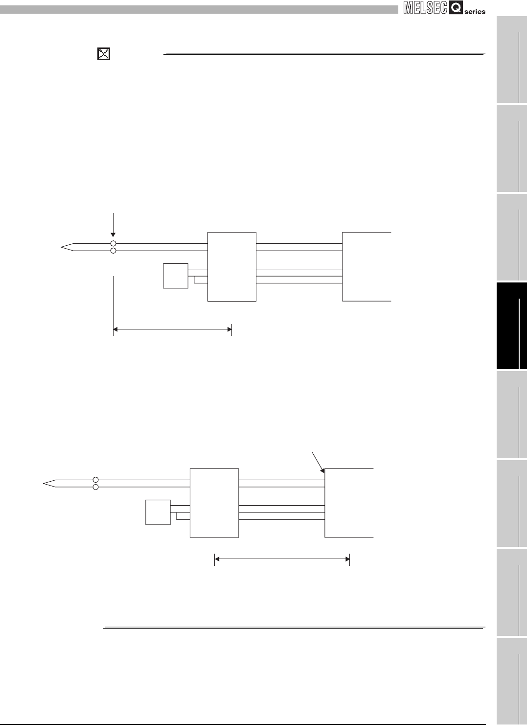
In the following cases (1) and (2), the cold junction temperature compensation
resistor (RTD) and the end part of a thermocouple (or the end part of a
compensating lead wire) are not connected to the same part, the relay terminal
block. In such cases, the measured temperature value may be abnormal due to
ambient temperature difference.
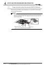
(1) As the following figure, when the end part of the thermocouple and relay
terminal block are connected by a cable, the measured temperature may be
abnormal due to ambient temperature difference between A and B.
Figure 4.5 When the end part of the thermocouple and relay terminal block are connected by a cable
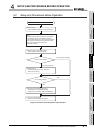
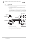
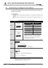
(2) As the following figure, when the relay terminal block and the Q68TD-G-H02
(H01) are connected by a compensating lead wire, the measured temperature
may be abnormal due to ambient temperature difference between B and C.
Figure 4.6 When the relay terminal block and the Q68TD-G-H02 (H01) are connected by a compensating lead wire
End part
A
B
RTD
(Correct) Compensating
lead wire
(Incorrect) Cable
Cable
Ambient temperature difference
Relay
terminal block
Q68TD-G-H02(H01)
A: End part of the thermocouple
B: Cold junction temperature
compensation resistor (RTD)
End part
CB
RTD
(Correct) Cable
(Incorrect)
Compensating
lead wire
Compensating lead wire
Ambient temperature difference
Relay
terminal block
Q68TD-G-H02(H01)
B: Cold junction temperature
compensation resistor (RTD)
C: End part of the compensating lead wire