


3 - 22
3.3 I/O Signals Transferred to/from Programmable Controller CPU
3.3.1 I/O signal list
3
SPECIFICATIONS
3.3 I/O Signals Transferred to/from Programmable Controller CPU
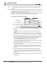
This section describes the I/O signal assignment and signal functions.
3.3.1 I/O signal list
The following are the I/O signals of the Q68TD-G-H02 (H01).
The I/O numbers (X/Y) given in this chapter and later assume that the first I/O number of
the Q68TD-G-H02 (H01) is set to 0.
POINT
The reserved signals marked *1 are used by the system and are unavailable for
the user. Should they be turned on/off in a sequence program, we cannot
guarantee the functions of the Q68TD-G-H02 (H01).
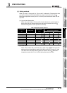
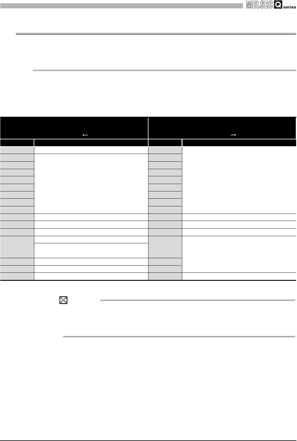
Table 3.8 I/O signal list
Input signal
(Signal direction:
Programmable controller CPU Q68TD-G-H02 (H01))
Output signal
(Signal direction:
Programmable controller CPU Q68TD-G-H02 (H01))
Device No. Signal name Device No. Signal name
X0 Module ready Y0
Reserved
*1
X1
Reserved
*1
Y1
X2 Y2
X3 Y3
X4 Y4
X5 Y5
X6 Y6
X7 Y7
X8 Y8
X9 Operating condition setting completion flag Y9 Operating condition setting request
XA Offset/gain setting mode status flag YA User range write request
XB Channel change completion flag YB Channel change request
XC
Disconnection detection signal (Q68TD-G-H02 only)
YC
Reserved
*1
Disconnection state monitor signal (Q68TD-G-H01
only)
XD Warning output signal YD
XE Conversion completion flag YE
XF Error flag YF Error clear request