4
SETUP AND PROCEDURES BEFORE OPERATION
4.3 Part Names
4 - 5
1
OVERVIEW
2
SYSTEM
CONFIGURATION
3
SPECIFICATIONS
4
SETUP AND
PROCEDURES BEFORE
OPERATION
5
UTILITY PACKAGE (GX
CONFIGURATOR-TI)
6
PROGRAMMING
7
ONLINE MODULE
CHANGE
8
TROUBLESHOOTING
* 1 When the module is mounted on a MELSECNET/H remote I/O station, the RUN LED stays off until
a data link starts normally, even after the power is turned on. The RUN LED turns on once a data
link starts.
* 1 For actual wiring, refer to Section 4.4.2 External Wiring.
(3) Connector for external wiring
The connectors for use with the Q68TD-G-H02 (H01) should be purchased separately
by the user.
The following tables show the connector types and the crimp-contact tool.
Table 4.2 Part names
Number Name Description
1) RUN LED
Displays the operating status of the Q68TD-G-H02(H01).
On : Normal operation
Flashing : During offset/gain setting mode
Off :
5V power supply interrupted, watchdog timer error occurred, or online module
change enabled.
2) ERR. LED
Displays the error status of the Q68TD-G-H02(H01).
On : Error
Flashing : Error in switch settings
Switch No. 5 of the intelligent function module has been set to a value other
than zero.
Off : Normal operation
3) ALM LED
Displays the warning status of the Q68TD-G-H02(H01).
On : Warning (process alarm, rate alarm) occurring (Refer to Section 3.4.13)
Flashing :
Disconnection detected (Q68TD-G-H02)
Checking a disconnection status (Q68TD-G-H01)
Off : Normal operation
4) Serial No. display Displays the serial No. of the Q68TD-G-H02 (H01).
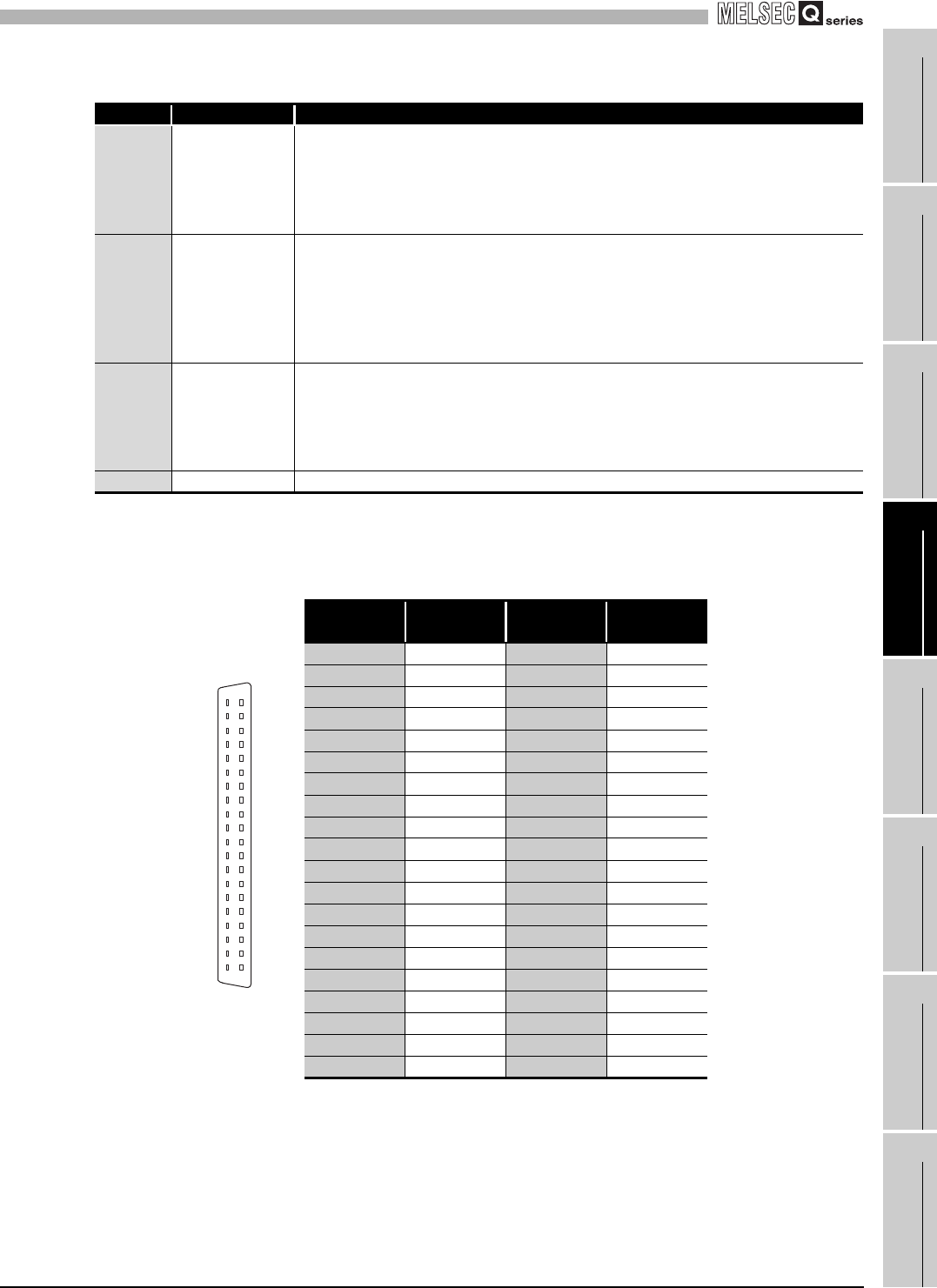
Table 4.3 Signal name
Terminal
number
Signal name
Terminal
number
Signal name
A1 CH1+ B1 CH1-
A2 --- B2 ---
A3 CH2+ B3 CH2-
A4 --- B4 ---
A5 CH3+ B5 CH3-
A6 --- B6 ---
A7 CH4+ B7 CH4-
A8 --- B8 ---
A9 CH5+ B9 CH5-
A10 --- B10 ---
A11 CH6+ B11 CH6-
A12 --- B12 ---
A13 CH7+ B13 CH7-
A14 --- B14 ---
A15 CH8+ B15 CH8-
A16 --- B16 ---
A17 --- B17 ---
A18 --- B18 ---
A19 --- B19 RTD+
A20 RTDG B20 RTD-
B20
B19
B18
B17
B16
B15
B14
B13
B12
B11
B10
B9
B8
B7
B6
B5
B4
B3
B2
B1
A20
A19
A18
A17
A16
A15
A14
A13
A12
A11
A10
A9
A8
A7
A6
A5
A4
A3
A2
A1
Seen from the front
of the module
Figure 4.3 Terminal
number


