


2
SYSTEM CONFIGURATION
2.1 Applicable Systems
2 - 4
1
OVERVIEW
2
SYSTEM
CONFIGURATION
3
SPECIFICATIONS
4
SETUP AND
PROCEDURES BEFORE
OPERATION
5
UTILITY PACKAGE (GX
CONFIGURATOR-TI)
6
PROGRAMMING
7
ONLINE MODULE
CHANGE
8
TROUBLESHOOTING
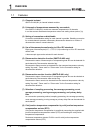
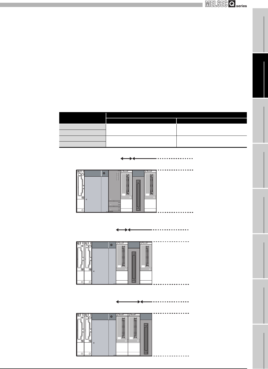
(b) Restriction on mountable slot position of the Q68TD-G-H01
The Q68TD-G-H01 has restrictions on mountable slot position.
The following describes the restrictions of the slot position when mounting the
Q68TD-G-H01 with a combination of the power supply module and the base unit.
For the slot that the Q68TD-G-H01 cannot be mounted, leave the slot open or
mount a module other than the Q68TD-G-H01.
The combination use of modules other than the following power supply modules
and the base units does not have restrictions.
When using the Q68TD-G-H01 on the remote I/O station, the restriction is the
same as for the main base unit.
When failing to comply with the following restrictions, the accuracy might not be in
the specification range.
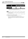
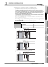
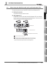
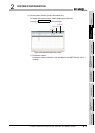
1)
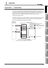
Figure 2.1 Mountable slot position of Q68TD-G-H01
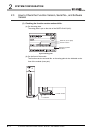
2)
Figure 2.2 Mountable slot position of Q68TD-G-H01
3)
Figure 2.3 Mountable slot position of Q68TD-G-H01
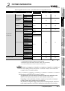
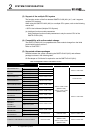
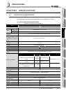
Table 2.3 Restriction on mountable slot position
Power supply module
Restrictions
Main base unit Extension base unit
Q63P
No restrictions
Mount the module to I/O slot No.1 or
later. 2)
Q63RP
Q64P Mount the module to I/O slot No.1 or
later. 1)
Mount the module to I/O slot No.2 or
later. 3)
Q64RP
OUT
I/01 I/01
CPU
Slot
No.0
Not mountable
Mountable
Power
supply
Slot
No.1
Slot
No.2
OUT
I/01 I/01
IN
Slot
No.0
Not mountable
Mountable
Power
supply
Slot
No.1
Slot
No.2
OUT
IN
I/01 I/01
Slot
No.0
Not mountable Mountable
Slot
No.1
Slot
No.2
Power
supply