


8
TROUBLESHOOTING
8.2 Troubleshooting
8.2.9 Measured temperature value is abnormal
8 - 6
1
OVERVIEW
2
SYSTEM
CONFIGURATION
3
SPECIFICATIONS
4
SETUP AND
PROCEDURES BEFORE
OPERATION
5
UTILITY PACKAGE (GX
CONFIGURATOR-TI)
6
PROGRAMMING
7
ONLINE MODULE
CHANGE
8
TROUBLESHOOTING
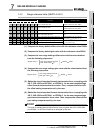
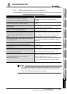
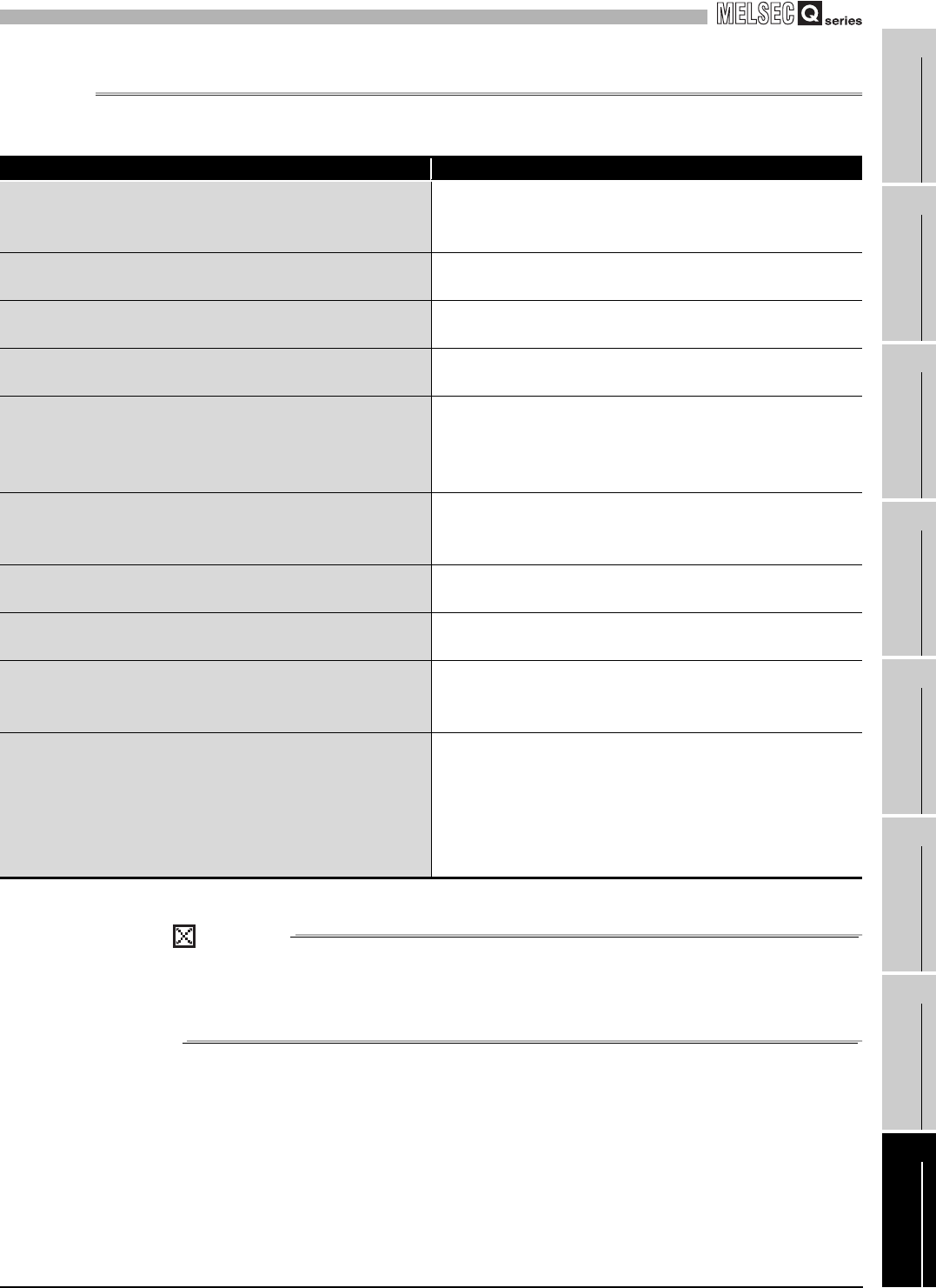
8.2.9 Measured temperature value is abnormal
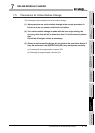
POINT
The module may be faulty if the measured temperature values cannot be read
after proper corrective actions have been taken according to the above check
items. Consult the nearest representative or branch.
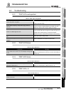
Table 8.10 Measured temperature value is abnormal
Check Item Remedy
Check whether the connected thermocouple or
compensation conductor differs from the setting.
Set the thermocouple type connected to the switch 1 or 2 in
the intelligent function module switch setting of GX
Developer.
Check whether the connected thermocouple or
compensation conductor is connected reversely.
Connect the thermocouple or compensation conductor
correctly.
Check the wiring.
Refer to Section 4.4.2 (1) Wiring procedure, and wire cables
and compensating lead wires correctly.
Check for noise in the thermocouple input.
Check influence from the ground and adjacent devices, and
take action to prevent noise.
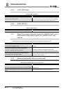
Check the cold junction temperature compensation resistor
(RTD) for making cold junction temperature compensation for
wire disconnection or disconnection from the relay terminal
block.
Check that the cold junction temperature compensation
resistor (RTD) is connected to the relay terminal block and
there is continuity, and if not, connect or change the cold
junction temperature compensation resistor (RTD).
Check whether the cold junction temperature compensation
yes/no setting is correct.
Set the switch 4 to the correct position in the intelligent
function module switch setting of GX Developer. (Refer to
Section 4.5.)
Check whether conversion is made with the other
thermocouple set after setting of the offset/gain value
Make offset/gain setting again after changing the
thermocouple.
Check whether wiring between the module and terminal
block is correct.
Check that wiring between the module and terminal block is
performed correctly.
The Q68TD-G-H01 module was mounted in the limited
position in the system using the power supply module of the
Q63P, Q63RP, Q64P or Q64RP.
Refer to Section 2.1 (2) Restrictions on mountable slot
position in which the module can be installed.
Check whether the wiring resistance value of the
thermocouple is not high.
• Check the wiring resistance value of the thermocouple and
whether a temperature error is caused by the wiring
resistance. (Refer to Section 3.1 (2).)
• Use the offset/gain setting to correct the temperature error
caused by the wiring resistance value. (Refer to Section
4.6.)