


6 - 5
6.2 Using Programs in Normal System Configuration
6.2.1 Before creating a program
6
PROGRAMMING
6.2.1 Before creating a program
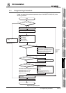
This section describes the steps to be taken before creating a program.
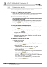
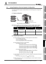
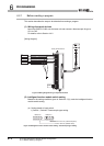
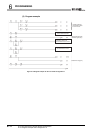
(1) Wiring of external devices
Mount the Q68TD-G-H02 onto the base unit and connect a thermocouple K type to
CH1 to CH3.
For details, refer to Section 4.4.2.
[Wiring diagram]
]
Figure 6.3 Wiring diagram using a relay terminal block
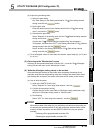
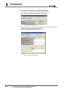
(2) Intelligent function module switch setting
Based on the setting conditions given in Section 6.2 (2), make the intelligent function
module switch setting.
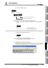
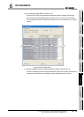
(a) Setting details of each switch
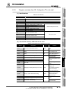
1) Switch 1, Switch2: Thermocouple type setting
Figure 6.4 Intelligent function module switch setting: Thermocouple type setting
CH1
Thermocouple
CH2
Thermocouple
CH3
Thermocouple
Relay terminal block
RTD
CH4 CH3CH2 CH1
H
0000
CH6 CH5CH8CH7
H
0000
<Switch 2>
<Switch 1>
CH1 to CH3: 0
H (Thermocouple K)
CH4 to CH8: 0
H (Default value)