


6
PROGRAMMING
6.2 Using Programs in Normal System Configuration
6 - 4
1
OVERVIEW
2
SYSTEM
CONFIGURATION
3
SPECIFICATIONS
4
SETUP AND
PROCEDURES BEFORE
OPERATION
5
UTILITY PACKAGE (GX
CONFIGURATOR-TI)
6
PROGRAMMING
7
ONLINE MODULE
CHANGE
8
TROUBLESHOOTING
6.2 Using Programs in Normal System Configuration
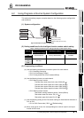
This section describes program examples based on the following system configuratiion
and conditions.
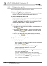
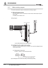
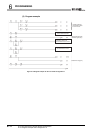
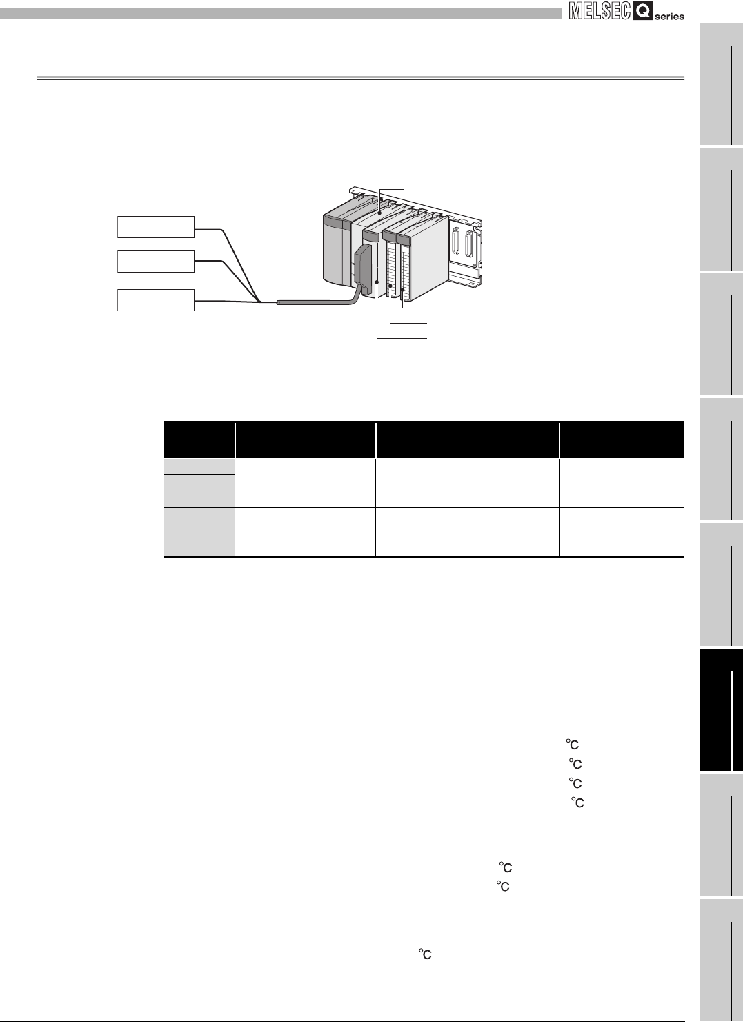
(1) System configuration
Figure 6.2 Example of system configuration
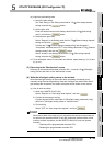
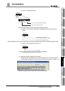
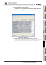
(2) Setting conditions for the intelligent function module switch setting
(3) Programming conditions
(a) Use the following temperature conversion system for each channel.
• CH1: Sampling processing
• CH2: Count average (5 times)
• CH3: Primary delay filter (Time constant 960ms)
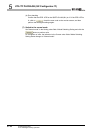
(b) Use the following function at each channel.
• CH2: Warning output function
• CH3: Warning output function
(c) Use the following setting for the Conversion setting for disconnection detection of
CH1 to CH3.
• CH1 to CH3: Down scale (-352.0 ) [Default setting]
(d) When a write error occurs, the corresponding error code is output to an output
module in BCD value.
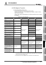
Table 6.1 Setting conditions for the intelligent function module switch setting
Channel
Thermocouple type
(Measurement range)
Offset/gain setting
Cold junction
compensation
CH1
Thermocouple K Factory default setting Available
CH2
CH3
CH4
to
CH8
Not used - -
Process alarm lower lower limit value: 2000 (200 )
Process alarm lower upper limit value: 2050 (205 )
Process alarm upper lower limit value: 2950 (295 )
Process alarm upper upper limit value: 3000 (300 )
Rate alarm warning detection period: 3 times (960ms)
Rate alarm lower limit value: -50 (-5.0 )
Rate alarm upper limit value:50 (+5.0 )
CH1
Thermocouple
CH2
Thermocouple
CH3
Thermocouple
QCPU
QY10 (Y20 to Y2F)
QX10 (X10 to X1F)
Q68TD-G-H02 (X/Y0 to X/YF)