


4
SETUP AND PROCEDURES BEFORE OPERATION
4.6 Offset/Gain Setting
4 - 13
1
OVERVIEW
2
SYSTEM
CONFIGURATION
3
SPECIFICATIONS
4
SETUP AND
PROCEDURES BEFORE
OPERATION
5
UTILITY PACKAGE (GX
CONFIGURATOR-TI)
6
PROGRAMMING
7
ONLINE MODULE
CHANGE
8
TROUBLESHOOTING
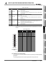
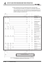
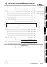
* 1 When inputting a value using such as a standard DC voltage generator, or using without cold
junction temperature compensation on actual use, set it to "without cold junction compensation".
* 2 The mode switching (normal mode to offset/gain setting mode to normal mode) method is indicated
below.
* 3 For the conversion enable/disable setting of unused channels or channels not executing the offset/
gain setting, always set it to "disable".
If all channels are set to "Enable", Disconnection detection flag (Disconnection state monitor flag)
(Un\G49) of channels that are not connecting a thermocouple turns on (changes to "1")
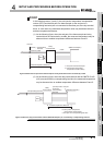
* 4 Buffer memory address of channel 1 only is indicated in the chart. For buffer memory address of
other channels, refer to Section 3.4.1 Buffer memory assignment.
* 5 Do not perform the operations below during the steps indicated with *5. If they are performed, the
data inside a flash memory will have a problem, and the Q68TD-G-H02 (H01) may not operate
normally.
• Powering off the programmable controller CPU
• Resetting the programmable controller CPU
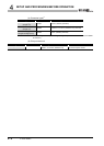
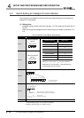
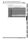
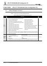
Table 4.5 Mode switching method
Mode switching method Refer to
Dedicated instruction (G(P).OFFGAN)
(2)(a) in this
section
Setting the mode switching setting (Un\G158, Un\G159) and turning from
OFF to ON the operating condition setting request (Y9).
(2)(b) in this
section
Intelligent function module switch setting
(After setting the intelligent function module switch, reset or turn from OFF
to ON the programmabel controller CPU.)
Section 4.5,
(2)(c) in this
section