


Instruction Manual
IB-106-300NH Rev. 4.3
May 2005
6-8 Troubleshooting Rosemount Analytical Inc. A Division of Emerson Process Management
World Class 3000
6-7 MPS PROBLEM
MPS problems can occur with a status of C Err,
R Hi, TGLow. The O
2
reading can be 0% to
99%, and probe data will be in the normal
ranges. Consider two conditions, A and B.
Refer to Table 6-5 to troubleshoot problems with
the MPS.
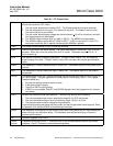
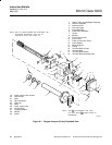
Table 6-5. MPS Troubleshooting
Problem
Cause
Corrective Action
Status is NoGas.
Cell mV is between -20 to 120 mV.
1. Regulator or plumbing fault. The test gas pressure is low for the indicated probe [20 to 25 psig (138 to
172 kPa gage)].
Check test gas pressure [should be 20 psig (138 kPa gage)], regulator, and lines. Reset, repair,
or replace the regulator as needed. If only one probe has low flow [less than 5 scfh (2.4 L/min)],
check lines, needle valve, connectors, and MPS solenoid for that probe.
2. Test gas low.
Replace empty test gas cylinder with full cylinder. Verify O
2
concentration.
3. Wiring fault.
Confirm proper wiring and continuity between MPS and electronics. Repair as needed.
4. Pressure switch fault.
Pressure switch is factory set at 16 psig (68.9 kPa gage). Set test gas regulator pressure to 20
psig (138 kPa gage) to avoid nuisance alarms. Replace faulty switch with a new one if test gas
supply is good.
Status is ResHi or CalEr.
Cell mV is between -20 to 120 mV.
The CalEr occurs when the slope calculated from the last calibration was out of range. CalEr can be
caused by leaks, a faulty diffusor or sensor cell, erroneous test gas values, or not enough test gas time.
Each test gas should be supplied for at least three minutes.
1. Flowmeter set incorrectly.
The flowmeter for each probe must be set individually. Flow should be 5 scfh (2.4 L/min).
2. Wiring fault.
Confirm proper wiring and continuity between MPS and electronics.
3. Piping fault. Faulty gas line or regulator.
Check gas line, valves, and regulators for blockage or corrosion. Repair or replace as needed.
4. Solenoid fault.
Verify nominal 24 VDC at HI GAS, LOW GAS, IN CAL, and CAL RET connections. Voltages
should drop to about 4 VDC. If voltage is present but solenoid does not work, replace the
solenoid.
5. Termination board fault.
Verify 24 VDC at J11 on termination board. Repair or replace termination board or connectors as
needed.
6. Power supply fault.
Verify power supply fuses and output are good and that line voltage is present at J1. Repair or
replace the power supply as needed.
7. Power fault.
Check fuses, mains, and circuit breakers. Repair or replace as needed.