


Instruction Bulletin
Appendix D Rev. 2.5
May 2005
Rosemount Analytical Inc. A Division of Emerson Process Management Appendices D-7
World Class 3000
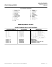
SERVICE AND NORMAL MAINTENANCE
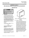
D-5 OVERVIEW
This section describes service and routine
maintenance of the MPS 3000 Multiprobe Cali-
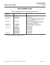
bration Gas Sequencer. Replacement parts re-
ferred to are available from Rosemount
Analytical. Refer to Table D-3 for part numbers
and ordering information.
Install all protective equipment covers
and safety ground leads after equip-
ment repair or service. Failure to in-
stall covers and ground leads could
result in serious injury or death.
D-6 FUSE REPLACEMENT
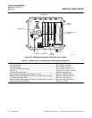
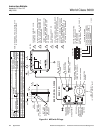
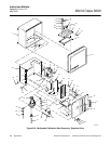
Power supply (58, Figure D-6) contains two
identical 1 amp fuses (3). Perform the following
procedure to check or replace a fuse.
Disconnect and lock out power before
working on any electrical components.
a. Turn off power to the system.
b. Unscrew top of fuseholder (40) and remove
the fuse. Refer to Table D-3 for replacement
fuse specifications. After checking or re-
placing a fuse, reinstall top of fuseholder.
D-7 POWER SUPPLY REPLACEMENT
Disconnect and lock out power before
working on any electrical components.
a. Turn off power to the system.
b. Loosen two captive screws holding the MPS
cover (15, Figure D-6). Open the MPS
cover.
c. Loosen two captive screws holding the inner
cover (16). Lower the inner cover.
d. Disconnect the 24V connector from J11 on
the termination board (34).
e. Remove two screws (39) and washers (38)
holding the terminal cover (37). Remove the
terminal cover.
f. Tag and remove wires from terminals 1 and
4 or 5 of the transformer in the power supply
(58).
g. Remove two nuts (60) and washers (59)
from the screws holding the power supply
(58). Remove the power supply.
h. Mount the new power supply onto the
screws with two nuts (60) and washers (59).
Make sure the ground wires are connected
to the upper mounting screw.
i. Reconnect the wires removed in step f.
j. Install the terminal cover (37) with two
screws (38) and washers (39).
k. Connect the 24V connector to J11 on the
termination board (34).
l. Close and secure the inner cover (16) with
two captive screws. Close and secure the
outer cover (15) with two captive screws.
D-8 SOLENOID VALVE REPLACEMENT
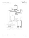
An MPS 3000 will always have a HI GAS sole-
noid (63, Figure D-6) and a LOW GAS solenoid
(64) mounted to the manifold (11). Each probe
will also have a solenoid valve (9) mounted on
the manifold.
Disconnect and lock out power before
working on any electrical components.
a. Turn off power to the system.
b. Loosen two captive screws holding the MPS
cover (15, Figure D-6). Open the MPS
cover.
c. Loosen two captive screws holding the inner
cover (16). Lower the inner cover.
d. Disconnect the HI GAS (J17), LOW GAS
(J18), or Probe (J13-J16) plug from its re-
ceptacle on the termination board (34).