


Instruction Bulletin
Appendix A Rev. 3.9
May 2005
Rosemount Analytical Inc. A Division of Emerson Process Management Appendices A-17
World Class 3000
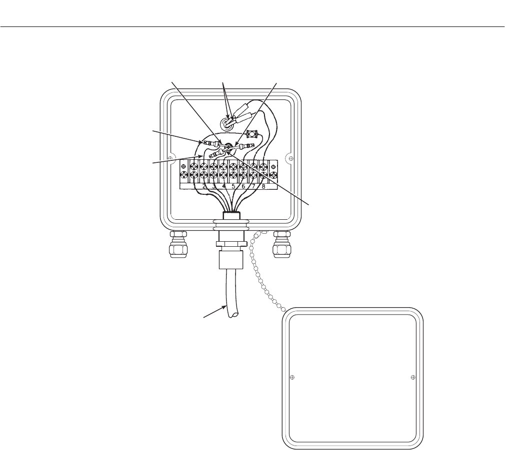
CELL EXTENSION
WIRE (ORANGE)
BOMB TAIL
CONNECTOR
INCONEL
CELL WIRE
(CLEAR
SLEEVING)
HEATER
WIRES
(BLACK
SLEEVING)
THERMOCOUPLE -
(RED ALUMEL)
THERMOCOUPLE +
(YELLOW CHROMEL)
CALIBRATION
GAS FITTING
REFERENCE
AIR FITTING
PROBE JUNCTION
BOX COVE
R
CABLE
27270019
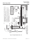
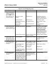
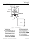
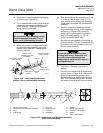
Figure A-18. Cell Wiring Connection
b. If the probe uses the standard diffusion
element, use a spanner wrench to remove
the diffusion element.
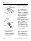
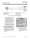
c. If equipped with the optional ceramic diffusor
assembly, remove and discard setscrews,
Figure A-19, and remove vee deflector. Use
spanner wrenches from probe disassembly
kit, Table A-3, to turn hub free from retainer.
Inspect diffusion element. If damaged, re-
place element.
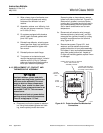
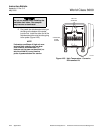
d. Loosen four socket head cap screws from
the cell and flange assembly and remove
the assembly and the corrugated seal. The
cell flange has a notch which may be used
to gently pry the flange away from the
probe. Note that the contact pad inside the
probe will sometimes fuse to the oxygen
sensing cell. If the cell is fused to the con-
tact pad, push the cell assembly back into
the probe (against spring pressure), and
quickly twist the cell assembly. The cell and
contact pad should separate. If the contact
pad stays fused to the cell, a new con-
tact/thermocouple assembly must be in-
stalled. Disconnect the cell and the
thermocouple wires at the probe junction
box, and withdraw the cell with the wires still
attached (see paragraph A-13).