


Instruction Bulletin
Appendix A Rev. 3.9
May 2005
Rosemount Analytical Inc. A Division of Emerson Process Management Appendices A-21
World Class 3000
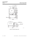
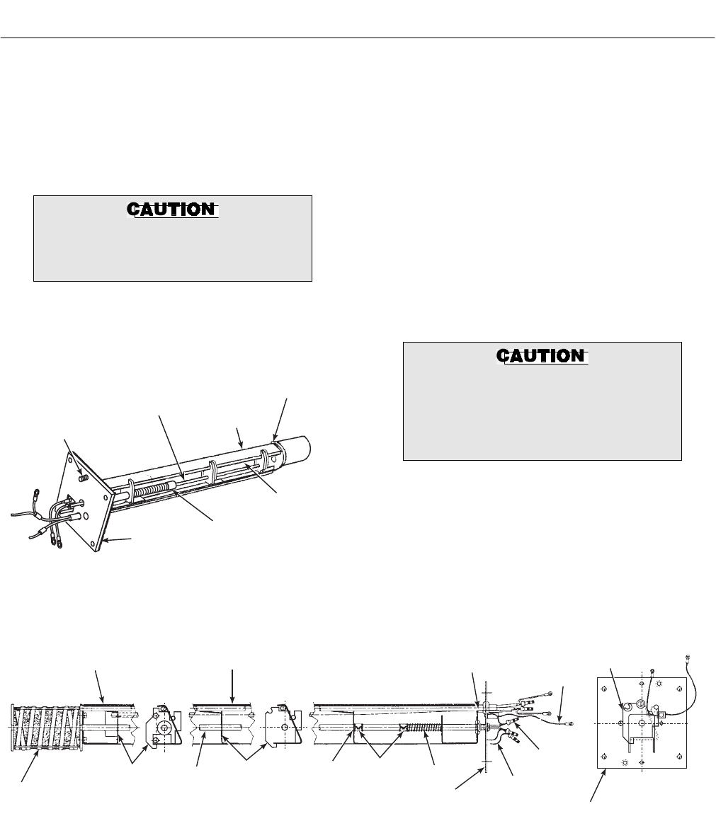
d. Use a pencil to mark locations of spring clip
on ceramic rod, Figure A-22.
e. Pry or squeeze tabs on spring clips, and pull
contact and thermocouple assembly out of
probe assembly. Retain spring clips and
spring; replace if damaged.
Be very careful when handling contact
and thermocouple assembly. The ce-
ramic rod in this assembly is fragile.
f. While very carefully handling new contact
and thermocouple assembly, lay old as-
sembly next to new one. Transfer pencil
marks to new rod.
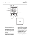
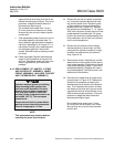
21240010
MOUNTING SCREW
(REAR VIEW)
CONTACT AND
THERMOCOUPLER
ASSEMBLY
V-STRUT
HEATER SCREWS
(NOT SHOWN)
HEATER
CERAMIC ROD
SPRING
CLIP
INSULATING
GASKET
Figure A-22. Inner Probe Replacement
(Heater, V-Strut, and Backplate Assembly)
g. Note wire lengths of old assembly as an aid
for trimming new lengths in step (j). Trim-
ming of wires will not always be necessary.
Throw away old contact and thermocouple
assembly.
h. Carefully guide new contact and thermo-
couple assembly through V-strut assembly
leaf spring (4, Figure A-23), spring (9),
spring clip (10) (held open by squeezing
tabs), and tube supports (11, 13) until
spring clip reaches pencil mark.
i. Reinstall insulating gasket on backplate, re-
place two screws, O-rings, lockwashers and
flat washers connecting probe junction box
to inner probe assembly.
Do not trim new wiring shorter than
existing (old) wiring. Excessive wire
trim will prevent connections from
being properly made and will require a
new replacement kit.
j. Trim wires, if necessary, as noted in
step (g).
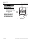
k. Connect color coded wires to proper termi-
nals as shown in Figure A-18. Rosemount
Analytical recommends connecting the
thermocouple wires directly to the terminal
strip. This is because the junction of differ-
ent metals at the wires and lugs and at the
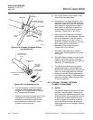
1
3
4
5
4
8
6
7
8
9
1011
11
2
13
12
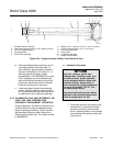
1. Heater Ceramic Rod
2. Contact and Thermocouple Assembly
3. Strut
4. Leaf Spring
5. Ring Lug
6. Butt Connector
7. Extension
8. Backplate
9. Spring
10. Spring Clip Assembly
11. Common Tube Support
12. Heater
13. Short Tube Support
Figure A-23. Heater, Strut, and Backplate Assembly
(Inner Probe Assembly)