


Instruction Manual
IB-106-300NH Rev. 4.3
May 2005
2-10 Installation Rosemount Analytical Inc. A Division of Emerson Process Management
World Class 3000
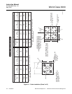
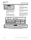
Do not install jumper JM6 on the mi-
croprocessor board, or JM1 on the in-
terconnect board, if an HPS is
installed in the system. This will result
in system failure.
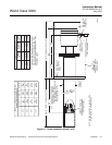
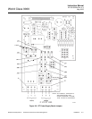
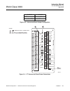
3. The IFT must have JM6 on the micro-
processor board (Figure 2-8 and Figure
2-9) and JM1 on the interconnect
board (Figure 2-10 and Figure 2-11)
installed if an HPS is not installed in
the system.
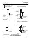
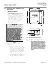
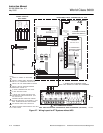
4. If an MPS is not used in the system,
wire jumper between CAL RET and
NO GAS must be installed on the in-
terconnect board. Remove wire jumper
if MPS is installed in the system. Refer
to Figure 2-7, note 6.
5. The power cable should comply with
the safety regulations in the user's
country and should not be smaller than
16 gauge, 3 amp.
6. Before supplying power to the IFT, ver-
ify that the jumpers have been properly
set in the IFT (Figure 2-5, Figure 2-8,
and Figure 2-10).
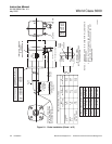
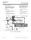
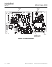
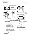
7. Terminal strip J5 on the power supply
board is used for supplying the IFT with
power. Terminal strip J6 on the power
supply board is used to supply the
probe heater with power if an HPS is
not used (Figure 2-6).
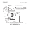
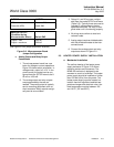
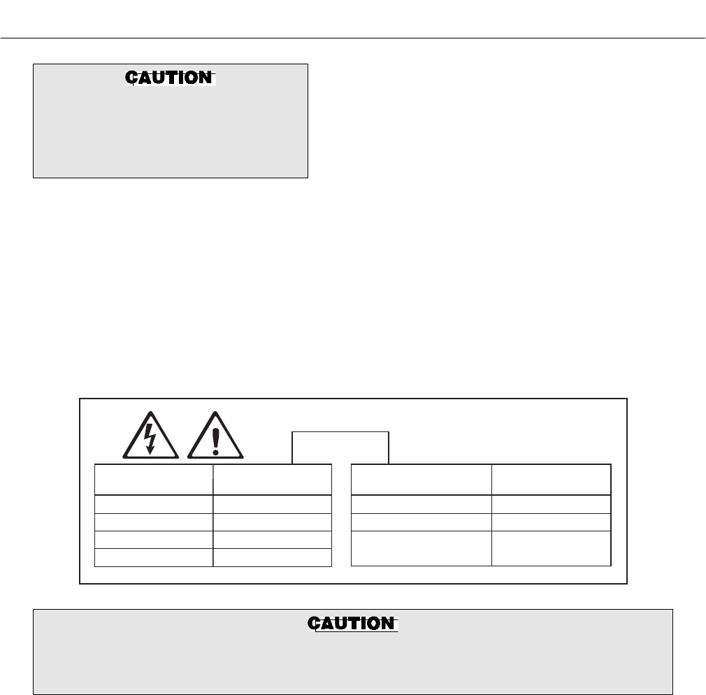
ALWAYS DISCONNECT LINE VOLTAGE
FROM INTELLIGENT FIELD TRANSMITTER
BEFORE CHANGING JUMPERS.
JUMPER
CONFIGURATION
LINE VOLTAGE
SELECTION
JUMPER
(INSTALL)
PROBE HEATER
VOLTAGE SELECTION
JUMPER
(INSTALL)
100 V.A.C.
120 V.A.C.
220 V.A.C.
240 V.A.C.
JM3, JM7, JM2
JM8, JM7, JM1
JM6, JM5, JM2
JM6, JM5, JM1
WORLD CLASS PROBE (44V)
WORLD CLASS "DIRECT
REPLACEMENT" PROBE (115V)
218 PROBE (115V)
JM10
JM9
JM9
21190012
If incorrect heater voltage is selected, damage to the probe may occur. For HPS voltage se-
lection jumper, refer to Figure 2-15. Always update the relevant labeling to reflect the set
voltage.
Figure 2-5. Power Supply Board Jumper Configuration