


Instruction Bulletin
Appendix E Rev. 4.6
May 2005
Rosemount Analytical Inc. A Division of Emerson Process Management Appendices E-1
World Class 3000
APPENDIX E, REV. 4.6
IFT 3000 INTELLIGENT FIELD TRANSMITTER
DESCRIPTION
Read the “Safety instructions for the
wiring and installation of this appara-
tus” at the front of this Instruction
Bulletin. Failure to follow the safety
instructions could result in serious
injury or death.
E-1 DESCRIPTION
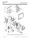
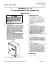
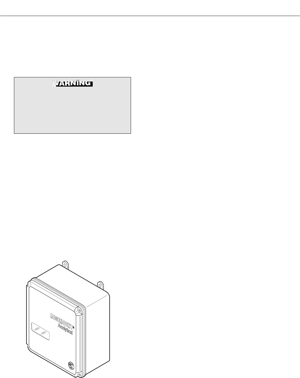
The Rosemount Analytical IFT 3000 Intelligent
Field Transmitter (IFT), Figure E-1, provides all
necessary intelligence for controlling a probe
and the optional Multiprobe Calibration Gas Se-
quencer. The IFT provides a user-friendly,
menu-driven operator interface with context-
sensitive, on-line help. The IFT may also be
used without an HPS.
The IFT is based on a modular design. There is
a maximum total of four PC boards within the
IFT. Every IFT contains a microprocessor
board, a power supply board, and an intercon-
nect board. In addition to these boards, deluxe
version IFTs also contain a General User Inter-
face/LED display board.
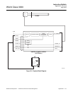
37840023
Figure E-1. IFT 3000 Intelligent Field Transmitter
a. Microprocessor Board
The microprocessor board contains,
EEPROM, RAM, and a timer. The micro-
processor board also controls the probe
heater. The IFT can be used in conjunction
with or without an optional HPS 3000
Heater Power Supply providing power to the
heater depending upon the user's
application.
b. Interconnect Board
The interconnect board is used for all com-
munications from the IFT to the other com-
ponents within the system. These other
components may include an optional HPS
3000 Heater Power Supply, optional MPS
Multiprobe Calibration Gas Sequencer,
World Class 3000 Probe (non-HPS
equipped system), analog output, and relay
outputs.
c. Power Supply Board
The power supply board is user configur-
able for five different line voltages to include
100, 120, 220, and 240 Vac. In addition, the
output voltage for a probe heater is also
configurable if used in a non-HPS equipped
system.
d. GUI/LED Display Board
The GUI/LED display board, which is part of
the GUI assembly, has a 4-line by 20-
character liquid crystal display and eight
membrane keys. The board also contains
an LED display which indicates the current
O
2
value. The LED display has indicator
LEDs for calibration gas high (TGH), cali-
bration gas low (TGL) and calibrating (CAL).
e. Heater (optional)
A heater is available for ambient conditions
below 32°F (0°C).