


Instruction Bulletin
Appendix E Rev. 4.6
May 2005
Rosemount Analytical Inc. A Division of Emerson Process Management Appendices E-13
World Class 3000
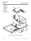
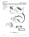
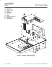
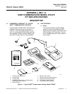
E-13 REPLACE TRANSFORMER
a. Unplug transformer connector plugs (not
shown) from power supply board (4, Figure
E-8).
b. Remove four screws (9), flat washers (10),
and internal lock washers (11).
c. Remove ground wire (12).
d. Remove transformer (13) from electronics
chassis (8).
e. Install new transformer (13) on electronics
chassis (8).
f. Assemble one screw (9), lock washer (11),
ground wire (12), and flat washer (10). In-
stall ground wire fasteners in mounting hole
of transformer (13) as shown.
g. Apply Loctite P/N 08431 thread locking
compound to leading threads of screws (9).
h. Secure transformer (13) with remaining
three screws (9), flat washers (10) and lock
washers (11).
i. Connect connector plugs of transformer (13)
to mating receptacles on power supply
board (4).
E-14 REPLACE HEATER AND THERMOSWITCH
Use the following instructions to replace a dam-
aged heater and thermoswitch assembly.
a. Unplug fan and heater connector plug from
power supply board (4, Figure E-8).
b. Heater and thermoswitch assembly (14) is
bonded to wall of electronics chassis (8).
Using alcohol solvent and putty knife, re-
move damaged heater and thermoswitch
assembly.
c. Cut heater lead wires (only) approximately
two inches (50 mm) from fan and heater
connector plug.
d. Strip 0.5 to 0.6 in. (13 to 15 mm) of insula-
tion from heater leads of connector plug.
e. Install one 2-in. (50 mm) length of heat
shrink tubing onto each lead of new heater
(14).
f. Connect and solder heater lead wires to
mating lead wires on fan and heater con-
nector plug. Center and install heat shrink
tubing over soldered wire connections.
g. Remove adhesive seal paper from back of
replacement heater (14). Carefully align and
adhere replacement heater on wall of elec-
tronics chassis (8) as shown.
h. Connect heater and fan connector plug to
mating receptacle on power supply board
(4).
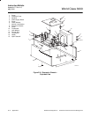
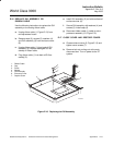
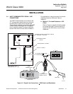
E-15 INSTALL ELECTRONICS CHASSIS
Use the following instructions to install the as-
sembled electronics chassis in the enclosure.
a. Place electronics chassis (3, Figure E-9) in
enclosure (4). Tighten captive screws (12).
b. Insert tabs of microprocessor assembly (10)
in mating slots of electronics chassis (3)
c. Slide microprocessor assembly (10) down
and install washer (9) and screw (8).
d. Plug heater and fan connector plug into
mating connector on power supply board
(13).
e. Plug two ribbon cables (5 and 6) into mating
connectors on microprocessor assembly
(10).