


Instruction Bulletin
Appendix D Rev. 2.5
May 2005
Rosemount Analytical Inc. A Division of Emerson Process Management Appendices D-1
World Class 3000
APPENDIX D, REV 2.5
MPS 3000 MULTIPROBE CALIBRATION GAS SEQUENCER
DESCRIPTION
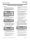
Read the “Safety instructions for the
wiring and installation of this appara-
tus” at the front of this Instruction
Bulletin. Failure to follow the safety
instructions could result in serious
injury or death.
D-1 DESCRIPTION
The Rosemount Analytical MPS 3000 Multi-
probe Calibration Gas Sequencer provides
automatic calibration gas sequencing for up to
four probes. The MPS routes calibration gas to
the selected probe under control of the CRE,
IFT, or digital electronics package. The elec-
tronics package can be preprogrammed by the
user for automatic periodic recalibration, or
manually initiated calibration through the keypad
on the front of the electronics package. The
calibration parameters held in the electronics
package can be selected to automatically up-
date after each
calibration.
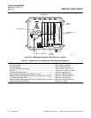
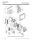
The MPS is housed in a NEMA 4X (IP56) non-
hazardous enclosure, Figure D-1.
NOTE
A single multichannel MPS cannot be
shared among a number of CRE
electronics.
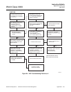
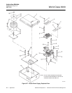
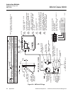
The MPS, Figure D-2, consists of: an air pres-
sure regulator, a terminal board, a flowmeter
assembly (one for each probe, up to four per
MPS), HI GAS solenoid, LO GAS solenoid, a
manifold, and a power supply. Each flowmeter
assembly contains a probe solenoid.
An optional Z-purge arrangement is available for
hazardous area classification. See Application
Data Bulletin AD 106-300B.
37840015
Analytical
Figure D-1. MPS 3000 Multiprobe Calibration Gas
Sequencer
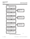
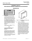
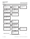
D-2 THEORY OF OPERATION
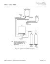
A typical automatic calibration setup is shown in
Figure D-3. The MPS 3000 Multiprobe Calibra-
tion Gas Sequencer operates under the control
of the CRE, IFT, or digital electronics package.
When the electronics package initializes auto-
matic calibration, the solenoid controlling the
selected probe is energized. Next, the solenoid
controlling calibration gas 1 (high O
2
) energizes
allowing calibration gas 1 to flow to that probe.
After the probe measures the oxygen concen-
tration of calibration gas 1, the gas solenoid is
deenergized. An operator selected time delay
allows the gas to clear the system. Next, the
solenoid controlling calibration gas 2 (low O
2
)
energizes and allows calibration gas 2 to flow to
the probe. After the probe measures the oxygen
concentration of calibration gas 2, the gas and
probe solenoids deenergize. The automatic
calibration is now complete for the probe
selected.