


Instruction Bulletin
Appendix A Rev. 3.9
May 2005
A-20 Appendices Rosemount Analytical Inc. A Division of Emerson Process Management
World Class 3000
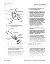
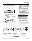
11. Wipe a heavy layer of anti-seize com-
pound onto the threads and mating
surfaces of the diffusion hub and
retainer.
12. Assemble retainer and diffusion hub
with two pin spanner wrenches. Torque
to 10 ft-lbs (14 N·m).
13. On systems equipped with abrasive
shield, install dust seal gaskets with
joints 180° apart.
14. Reinstall vee deflector, orienting apex
toward gas flow. Apply anti-seize com-
pound to setscrews and tighten with
hex wrench.
15. Reinstall probe on stack flange.
16. Turn power on to electronics and
monitor thermocouple output. It should
stabilize at 29.3 ±0.2 mV. Calibrate
probe per Instruction Bulletin applica-
ble to your electronics package.
A-13 REPLACEMENT OF CONTACT AND
THERMOCOUPLE ASSEMBLY
Use heat resistant gloves and cloth-
ing when removing probe junction box
and inner probe assembly. Do not at-
tempt to work on these components
until they have cooled to room tem-
perature. Probe components can be as
hot as 800°F (427°C). This can cause
severe burns.
Disconnect and lock out power before
working on any electrical components.
There is voltage up to 115 Vac.
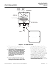
a. Disconnect and lock out power to electron-
ics. Using heat resistant gloves and cloth-
ing, remove probe junction box cover.
Squeezing tabs on hose clamps, remove
hoses from probe junction box, Figure A-21.
Remove four screws in corners of probe
junction box. Pull probe junction box and in-
ner probe assembly free from probe tube.
Set on bench and allow to cool to room
temperature.
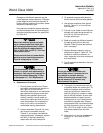
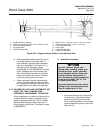
b. Disconnect cell extension wire (orange),
thermocouple wire (red alumel), and ther-
mocouple wire (yellow chromel) by cutting
bomb tail connections from the terminal
strip, Figure A-18.
c. Remove two screws, Figure A-21, lock-
washers, and flat washers that connect
probe junction box to inner probe assembly.
Pull heater, V-strut and backplate assembly
away from probe junction box. Inspect all
O-rings and insulating gasket; replace if worn
or damaged.
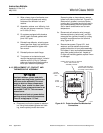
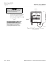
PROBE JUNCTION BOX
INNER PROBE ASSEMBLY
TO PROBE TUBE SCREWS
PROBE JUNCTION BOX TO HEATER,
STRUT, AND BACKPLATE
ASSEMBLY SCREW
PROBE
JUNCTION
BOX
HOSE
CLAMP
HOSE
21240027
Figure A-21. Probe Junction Box Mechanical
Connections