


Instruction Manual
IB-106-300NH Rev. 4.3
May 2005
2-16 Installation Rosemount Analytical Inc. A Division of Emerson Process Management
World Class 3000
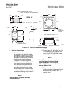
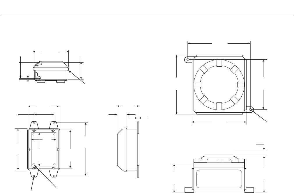
CLASS 1, DIVISION 1, GROUP B ENCLOSURE
#10-32 UNF 2A
THREADED INSERT
(0.31 x 0.31 FROM CORNER OF PLATE)
0.13" (3.3) THK U. L. APPROVED
GASKET
7.00
(177.8)
3.25
(82.6)
3.63
(92.2)
0.31
(7.9)
NEMA 4X
(NON-HAZARDOUS)
NOTE: DIMENSIONS IN INCHES
WITH MILLIMETERS IN PARENTHESES.
10.39
(264)
9.17
(233)
9.96
(253)
8.50
(215.9)
6.18
(156.9)
4.72
(120)
8.50
(215.9)
8.00
(203.2)
11.00
(279.4)
6.75
(171.5)
0.56 (14)
DIA (2)
MOUNTING
HOLES
1.00 (25.4) MINIMUM CLEARANCE
FOR REMOVING COVER
4.38
(111.3)
4.88
(124)
0.38
(9.7)
1.81
(46)
6.00
(152.4)
4.00
(101.6)
#0.31
686029
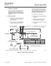
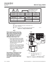
Figure 2-12. Outline of Heater Power Supply
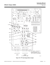
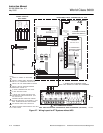
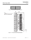
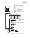
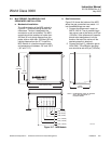
b. Electrical Connections
1. Electrical connections should be made
as described in the electrical installa-
tion diagram, Figure 2-13. The wiring
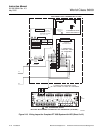
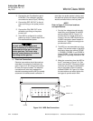
terminals are divided into two layers;
the bottom (FROM PROBE) terminals
should be connected first, the top
(FROM ELECTRONICS) terminals
should be connected last (Figure 2-14).
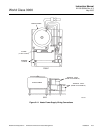
Each terminal strip has a protective
cover which must be removed when
making connections. To remove the
terminal covers, remove two slotted
screws holding cover in place. Always
reinstall terminal covers after making
connections. All wiring must conform to
local and national codes.
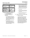
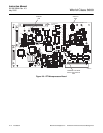
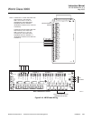
NOTE
Refer to Figure 2-16 for fuse locations
and specifications.
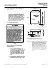
2. Power Input: 120, 220 or 240 Vac. For
120 Vac usage, install jumpers JM4
and JM1. For 220 or 240 Vac usage,
install jumper JM5 (see label, Figure
2-15).
NOTE
For 100 Vac usage, the heater power
supply is factory-supplied with a dif-
ferent transformer. When using the
HPS with 100 Vac transformer, install
jumpers JM1 and JM4.
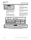
3. The power cable should comply with
safety regulations in the user's country
and should not be smaller than 16
gauge, 3 amp.