


Instruction Manual
IB-106-300NH Rev. 4.3
May 2005
4-4 Calibration Rosemount Analytical Inc. A Division of Emerson Process Management
World Class 3000
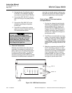
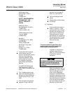
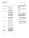
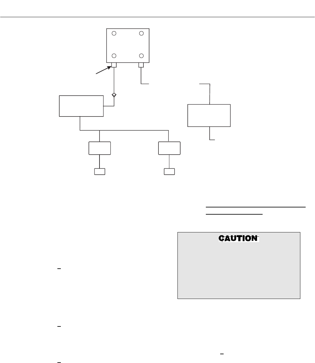
PROBE
(END VIEW)
CALIBRATION
IN-PLACE
FITTING
CHECK
VALVE
FLOW METER
LEAK TIGHT
VALVES
37840014
NOTE: PROBE CALIBRATION GAS FITTING
HAS A SEAL CAP WHICH MUST
BE IN PLACE AT ALL TIMES
EXCEPT DURING CALIBRATION.
REFERENCE
AIR SET
0.4% O
2
8.0% O
2
REFERENCE AIR
CONNECTION
2 SCFH
INSTR.
AIR
IN
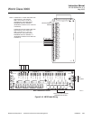
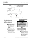
Figure 4-1. Typical Calibration Setup
NOTE
Only set the calibration gas flowmeter
upon initial installation and after
changing the diffusion element. A
slightly lower calibration gas flow rate
may indicate a plugged diffusion
element.
2 Set the calibration gas pres-
sure regulators and the flow
meter for a flow of 5 SCFH at
20 psi (138 kPa) for both
gases. The reference air
should be flowing as in normal
operation.
3 Refer to paragraph 4-2d of
this section for Manual (Semi-
automatic) Calibration setup
and procedure using the IFT.
4 Calibration gases will be
switched on and off using the
shutoff valves.
Test Method "B" Oxygen Calibration
Gas and Service Kit.
(a) Required Equipment
Do not use 100% nitrogen as a zero
gas. It is suggested that gas for the
zero be between 0.4% and 2.0% O
2
. Do
not use gases with hydrocarbon con-
centrations of more than 40 parts per
million. Failure to use proper gases
will result in erroneous readings.
NOTE
Ambient air is not recommended for
use as high calibration gas. An 8% O
2
balance in nitrogen is recommended
for high calibration gas.
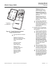
1 Portable Oxygen Calibration
Gas Kits (Figure 4-2), Rose-
mount Analytical P/N
6296A27G01, containing 8%
and 0.4% gases in a portable
carrying case with regulator,
built-in valve, hose and con-
necting adapter to the calibra-
tion gas connection.