


Instruction Bulletin
Appendix E Rev. 4.6
May 2005
E-2 Appendices Rosemount Analytical Inc. A Division of Emerson Process Management
World Class 3000
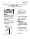
f. Z-Purge (optional)
A Z-purge arrangement is available for ap-
plications requiring hazardous area classifi-
cation. See Application Data Bulletin AD
106-300B.
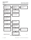
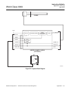
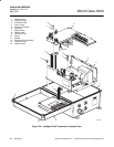
E-2 THEORY OF OPERATION
A functional block diagram of the IFT, con-
nected to the HPS and probe, is shown in
Figure E-2. In operation, the IFT monitors the
temperature of the cell by means of the probe
thermocouple. The IFT controls the temperature
of the cell. If the temperature of the cell be-
comes too high, the IFT will disable the HPS.
A cold junction temperature compensation fea-
ture ensures an accurate probe thermocouple
reading. A temperature sensor in the heater
power supply monitors the temperature at the
junction between the compensated cable run-
ning to the probe and the uncompensated cable
running to the IFT. The voltage from this sensor
is used by the IFT to compensate the probe
thermocouple readings for the temperature at
the junction.
The cell signal is a voltage proportional to the
oxygen concentration difference between the
two sides of the cell. The IFT receives this sig-
nal and translates it into a user-specified form
for display and/or output.
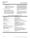
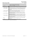
Table E-1. Specifications for Intelligent Field Transmitter
Environmental Classification..................................... NEMA 4X (IP56)
Humidity Range......................................................... 95% Relative Humidity
Ambient Temperature Range.................................... -20° to 122°F (-30° to 50°C)
Vibration.................................................................... 5 m/sec
2
, 10 to 500 xyz plane
Electrical Noise ........................................................ EN 61326, Class A
Installation Category ................................................. Overvoltage Category II (IEC 664)
HART Communications............................................ Modulated on a 4-20 mA analog output, only
Analog Outputs ......................................................... isolated, 0-20 mA, 4-20 mA, 0-10 V, 20-0 mA, 20-4 mA,
or 10-0 V output
O
2
Accuracy (analog output)..................................... 0.1% O
2
or ±3% of reading, whichever is greater using
Hagan calibration gases
O
2
Range................................................................... Field Selectable 0-40% (linear or logarithmic)
Power Supply............................................................ 100/120/220/240 ±10% Vac at 50/60 Hz.
Power Requirements................................................. (w/HPS 3000): 30 Watts (VA); (w/Model 218 Probe):
275 VA (w/WC 3000 Probe): 275 Watts (VA)
Output Resolution ..................................................... 11 bits (1 bit = 0.05% of output F.S.)
System Speed of Response (amplifier output) ......... less than 3 seconds
Resolution Sensitivity - Transmitted Signal .............. 0.01% O
2
Deadman Contact Output ......................................... Form-C, 48 Volt max, 100 mA max
Programmable Contact Outputs ............................... 2 available, Form-C, 48 V max, 100 mA max
GUI/LED Display Board ............................................ 1, with 0.8 in. (20 mm) high, 3-character, alphanumeric
LED display 4-line by 20-character backlight LCD
alpha-numeric display; 8-key general purpose key-
board, or HART device
Approximate Shipping Weight................................... 25 lbs (11 kg)