


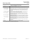

Instruction Bulletin
Appendix E Rev. 4.6
May 2005
Rosemount Analytical Inc. A Division of Emerson Process Management Appendices E-11
World Class 3000
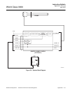
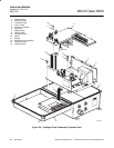
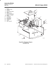
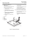
E-9 REPLACE MICROPROCESSOR BOARD
a. Remove four screws (1, Figure E-7) and
washers (2).
Pull very carefully on the microproc-
essor board to ensure that none of
the mating connector pins are dam-
aged.
b. Carefully unplug and remove microproc-
essor board (3) from interconnect board
(4).
c. Carefully line up connector of new micro-
processor board (3) and interconnect
board (4). Plug in mating connectors.
d. Secure microprocessor board (3) to
mounting plate (5) with screws (1) and
washers (2).
E-10 REPLACE INTERCONNECT BOARD
a. Carefully tag and remove the jumper
wires from terminal strip on interconnect
board (4, Figure E-7). Jumper wires must
be installed in same terminals on re-
placement interconnect board.
b. Remove screws (6) and washers (7).
Pull very carefully on the intercon-
nect board to ensure that none of
the mating connector pins are dam-
aged.
c. Carefully unplug and remove interconnect
board (4) from microprocessor board (3).
d. Carefully line up connector of new inter-
connect board (4) and microprocessor
board (3). Plug in mating connectors.
e. Secure interconnect board (4) to mount-
ing plate (5) with screws (6) and washers
(7).
f. Reconnect tagged jumper wires to mating
terminals of interconnect board (4).
E-11 REPLACE FAN
a. Remove screws (8, Figure E-7), self-
locking hex nuts (9), and fan (10) from
mounting plate (5).
b. Cut fan lead wires (only) at connector side
of installed heat shrink.
c. Strip 0.5 to 0.6 in. (13 to 15 mm) of wire
insulation from fan leads of fan and heater
connector plug (11).
d. Slide one 2-in. (50 mm) length of heat
shrink tubing onto each lead of fan (10).
e. Connect and solder lead wires of new fan
(10) to mating lead wires on fan and
heater connector plug (11). Install heat
shrink tubing over soldered lead wire
connections.
f. Attach fan (10) with screws (8) and self-
locking hex nuts (9) to mounting plate (5).
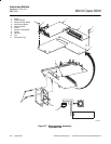
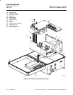
E-12 REPLACE POWER SUPPLY BOARD
a. Loosen two screws (1, Figure E-8) and
remove protective cover (2). Remove
standoffs (3).
b. Unplug transformer connector plugs (not
shown) from power supply board (4).
c. Remove three screws (5), two plastic
washers (6), and external lock washer (7).
Remove power supply board (4).
d. Install new power supply board (4) on
electronics chassis (8). Secure power
supply board with screws (5), washers (6
and 7), and standoffs (3).
e. Install protective cover (2) and screws (1)
to secure the cover.
f. Connect transformer connector plugs (not
shown) to mating receptacles on power
supply board (4).