


Instruction Manual
IB-106-300NH Rev. 4.3
May 2005
Rosemount Analytical Inc. A Division of Emerson Process Management Installation 2-9
World Class 3000
2-2 INTELLIGENT FIELD TRANSMITTER (IFT)
INSTALLATION
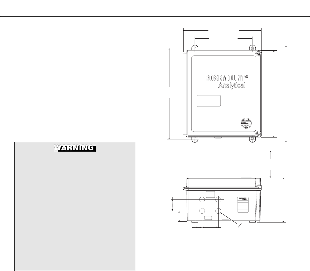
a. Mechanical Installation
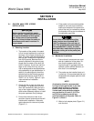
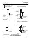
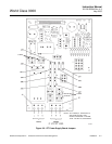
The outline drawing of the IFT module in
Figure 2-4 shows mounting centers and
clearances. The NEMA 4X enclosure is de-
signed to be mounted on a wall or bulk-
head. The IFT should be installed no more
than 1200 feet (364 m) from the optional
HPS or 150 feet (45 m) from the probe if
HPS is not installed in the system.
b. Electrical Connections
To meet the Safety Requirements of
IEC 1010 (EC requirement), and ensure
safe operation of this equipment, con-
nection to the main electrical power
supply must be made through a circuit
breaker (min 10A) which will discon-
nect all current carrying conductors
during a fault situation. This circuit
breaker should also include a me-
chanically operated isolating switch. If
not, then another external means of
disconnecting the supply from the
equipment should be located close by.
Circuit breakers or switches must
comply with a recognized standard
such as IEC 947.
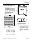
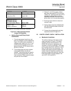
NOTE
Refer to Figure 2-6 for fuse locations
and specifications.
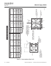
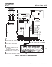
1. The IFT can be configured for 100,
120, 220, or 240 line voltages. For 120
Vac usage, install JM8, JM7, and JM1
on the power supply board. For 220
Vac usage, install jumpers JM6, JM5,
JM2 (refer to Figure 2-5 and Figure
2-6).
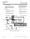
2. For installations where the cable run is
less than 150 feet (45 m), the IFT can
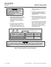
LINE
PROBE
NOTICE:
ALL CABLE SHOULD
BE RATED FOR USE
ABOVE 76 C
ModelIFT
Assy6A00178GXX
SN XXXXXXXXXXXX
VoltsXXX@50/60 Hz
LineFuse5Amps
Rosemount Analytical Inc.
P.O.Box 901, Orrville, OH
44667 USA
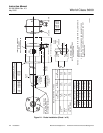
8.00 (203.2)
13.10
(332.7)
6.40
(162.6)
11.0 (279.4) MINIMUM DOOR
SWING CLEARANCE
NOTE: DESIGN DIMENSIONS ARE IN INCHES
WITH MILLIMETERS IN PARENTHESES.
37840020
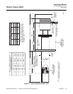
1.62
(41.1)
0.867
(22.00)
0
1.49
(37.8)
2.25
(57.15)
1.00
(25.4)
11.00 (279.4)
12.50
(317.5)
14.00
(355.6)
Figure 2-4. Outline of Intelligent Field Transmitter
be configured to connect directly to a
probe. An optional HPS is available for
cable runs over 150 feet (45 m). The
electrical connections for a non-HPS
equipped system should be made as de-
scribed in the electrical installation dia-
gram, Figure 2-7. Refer to Figure 2-13
for connections for an HPS equipped
system.