


Instruction Manual
IB-106-300NH Rev. 4.3
May 2005
ii Rosemount Analytical Inc. A Division of Emerson Process Management
World Class 3000
7-0 RETURN OF MATERIAL.............................................................................................. 7-1
8-0 APPENDICES ................................................................................................................. 8-1
Appendix A ......................................................................................................................A-1
Appendix B ......................................................................................................................B-1
Appendix D ......................................................................................................................D-1
Appendix E ......................................................................................................................E-1
Appendix J........................................................................................................................J-1
9-0 INDEX.............................................................................................................................. 9-1
LIST OF ILLUSTRATIONS
Figure 1. Complete World Class 3000 System.....................................................................P-5
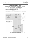
Figure 2. Wiring Layout for World Class 3000 System without HPS or MPS.......................P-8
Figure 1-1. Typical System Package ....................................................................................... 1-1
Figure 1-2. Typical System Installation .................................................................................... 1-5
Figure 1-3. World Class 3000 Typical Application with Intelligent Field Transmitters ............. 1-6
Figure 2-1. Probe Installation ................................................................................................... 2-2
Figure 2-2. Orienting the Optional Vee Deflector..................................................................... 2-7
Figure 2-3. Air Set, Plant Air Connection ................................................................................. 2-8
Figure 2-4. Outline of Intelligent Field Transmitter................................................................... 2-9
Figure 2-5. Power Supply Board Jumper Configuration ........................................................ 2-10
Figure 2-6. IFT Power Supply Board Jumpers....................................................................... 2-11
Figure 2-7. Wiring Layout for IFT Systems without HPS ....................................................... 2-12
Figure 2-8. Microprocessor Board Jumper Configuration..................................................... 2-13
Figure 2-9. IFT Microprocessor Board ................................................................................... 2-14
Figure 2-10. Interconnect Board Jumper Configuration........................................................... 2-15
Figure 2-11. IFT Interconnect Board Output Connections....................................................... 2-15
Figure 2-12. Outline of Heater Power Supply .......................................................................... 2-16
Figure 2-13. Wiring Layout for Complete IFT 3000 System with HPS..................................... 2-17
Figure 2-14. Heater Power Supply Wiring Connections .......................................................... 2-19
Figure 2-15. Jumper Selection Label ....................................................................................... 2-20
Figure 2-16. Jumpers on HPS Mother Board........................................................................... 2-20
Figure 2-17. MPS Module ........................................................................................................2-21
Figure 2-18. MPS Gas Connections ........................................................................................ 2-22
Figure 2-19. MPS Probe Wiring ............................................................................................... 2-23
Figure 4-1. Typical Calibration Setup....................................................................................... 4-4
Figure 4-2. Portable Rosemount Analytical Oxygen Calibration Gas Kit................................. 4-5
Figure 4-3. Typical Portable Calibration Setup ........................................................................ 4-6
Figure 4-4. Typical Automatic Calibration System ................................................................... 4-7
Figure 5-1. Deluxe Version IFT Displays and Controls............................................................ 5-2
Figure 5-2. Quick Reference Chart .......................................................................................... 5-5