


Instruction Bulletin
Appendix A Rev. 3.9
May 2005
Rosemount Analytical Inc. A Division of Emerson Process Management Appendices A-23
World Class 3000
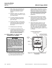
124
3
11
5
678 9
10
21240012
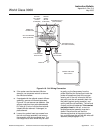
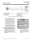
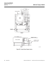
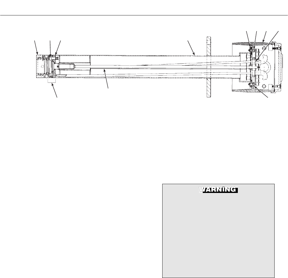
1. Snubber Diffusion Element
2. Socket Hd Cap Screw [0.25 in.-28 x 0.063 (16 mm)]
3. Cell and Flange Assembly
4. Corrugated Seal
5. Probe Tube Assembly
6. Gasket [4.0 in. (102 mm) x 4.0 in. x 0.12 in. (3 mm)]
7. Fillister Hd Screw [8-32 x 0.5 in. (12.7 mm)]
8. Cover Head Assembly
9. Hose Clamp
10. Lockwasher (#8 Split)
11. Heater Strut Assembly
Figure A-24. Oxygen Analyzer (Probe), Cross-Sectional View
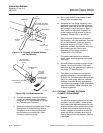
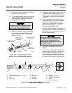
e. Slide assembled probe junction box and in-
ner probe assembly into probe tube. To
align calibration gas tube with correspond-
ing hole in backplate (A, B, Figure A-1), in-
sert aligning tool (included in probe
disassembly kit, P/N 3535B42G01) through
hole in backplate and into calibration gas
tube, while sliding the heater strut into the
probe tube. Secure with screws. Reinstall
hoses and probe junction box cover.
f. Power up system. Monitor thermocouple
output. It should stabilize at set point ±0.2
mV. Recalibrate probe per Instruction Bulle-
tin applicable to your electronics package.
A-15 CALIBRATION GAS AND REFERENCE AIR
LINES FOR HIGH TEMPERATURE -
CORROSIVE ENVIRONMENT OPERATION
A high temperature, corrosive environment kit is
available when the probe is exposed to these
types of operating conditions. The kit includes
stainless steel tubing and teflon fittings for in-
side the probe junction box. The kit part number
is 4843B93G01.
a. Installation Procedure
Use heat resistant gloves and
clothing when removing probe junc-
tion box and inner probe assembly.
Do not attempt to work on these com-
ponents until they have cooled to
room temperature. Probe components
can be as hot as 800°F (427°C). This
can cause severe burns.
Disconnect and lock out power before
working on any electrical components.
There is voltage up to 115 Vac.
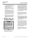
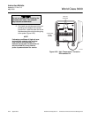
1. Disconnect and lock out power to digi-
tal electronics. Using heat resistant
gloves and clothing, remove probe
cover. Squeezing tabs on hose clamps,
remove hoses from probe junction box
(Figure A-21).