


Instruction Manual
IB-106-300NH Rev. 4.3
May 2005
Rosemount Analytical Inc. A Division of Emerson Process Management Calibration 4-1
World Class 3000
SECTION 4
CALIBRATION
4-1 ANALOG OUTPUT CALIBRATION
For the analog output to perform within the pub-
lished specifications, it must be manually cali-
brated. The only equipment needed to perform
the calibration is a voltage or current meter, de-
pending on which mode of operation is to be
calibrated. Prior to manual calibration, remove
the IFT from any control loops it may be in.
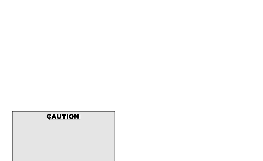
Prior to manual calibration, the IFT
should be removed from any auto-
matic control loops. Failure to remove
the IFT from control loops prior to
calibration may result in faulty equip-
ment performance.
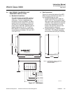
Once initiated from the Setup - Analog Outputs
menu, the calibration procedure is self guiding.
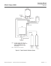
4-2 SYSTEM CALIBRATION
a. Overview
The primary purpose of an oxygen analyzer
is to give an accurate representation of the
percentage of O
2
in the gas stream. The
system should be calibrated periodically to
maintain an accuracy which may otherwise
be reduced over time due to cell aging. A
calibration record sheet is provided at the
end of this section to track cell performance.
A requirement for calibration is a set of two
accurate calibration gases spanning the
oxygen range of most interest. For example,
0.4% and 8% for a 0-10% oxygen range.
Under normal conditions the probe should
not need frequent calibration. Because cali-
bration is necessary, the system can be
equipped with the optional MPS 3000 Multi-
probe Calibration Gas Sequencer for fully
automatic calibration at regular intervals.
Without an MPS, the probes must be cali-
brated manually (semiautomatically).
b. Probe Calibration
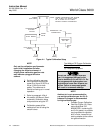
1. Previous Calibration Constants
Functionality
There are three sets of registers used
to store calibration constants. These
are: Latest Calibration, Previous Cali-
bration, and Calculation. Only the val-
ues in the Calculation register are used
to calculate the oxygen value for dis-
play and representation on the analog
output signal. These values may be
changed in two ways.
(a) The operator may change the val-
ues through the SETUP menu. The
operator may adjust the slope and
constant individually, or reset both
to the values calculated during the
last good calibration. To reset the
values, move the cursor to RESET
SLOPE & CONST and push
ENTER.
(b) The IFT will automatically change
the values after each calibration as
follows:
The values in the Latest Calibra-
tion registers are updated after
every complete calibration, even if
the calibration is not successful. If
the calibration is successful, the
values in the Latest Calibration
registers are copied into the Previ-
ous Calibration registers. This is
accomplished prior to the update of
the Latest Calibration registers.
The new slope and constant are
copied into the Calculation register.
If the calibration fails, the Previous
Calibration registers retain their
existing values, while the Latest
Calibration registers record the
values of the failed calibration. The
Calculation register is not updated
when the calibration fails.