


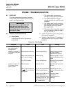

Instruction Bulletin
Appendix A Rev. 3.9
May 2005
A-16 Appendices Rosemount Analytical Inc. A Division of Emerson Process Management
World Class 3000
NOTE
!
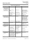
SERVICE AND NORMAL MAINTENANCE
UPON COMPLETING INSTALLATION, MAKE SURE THAT THE PROBE IS TURNED ON AND OPERATING
PRIOR TO FIRING UP THE COMBUSTION PROCESS. DAMAGE CAN RESULT FROM HAVING A COLD
PROBE EXPOSED TO THE PROCESS GASES.
During outages, and if possible, leave all probes running to prevent condensation and prema-
ture aging from thermal cycling.
If the ducts will be washed down during outage, MAKE SURE to power down the probes and
remove them from the wash area.
A-9 OVERVIEW
This section describes routine maintenance of
the oxygen analyzer probe. Spare parts referred
to are available from Rosemount Analytical.
Probe disassembly kit 3535B42G01 contains
the required spanner and hex wrenches. Refer
to the following section of this appendix for part
numbers and ordering information.
Install all protective equipment covers
and safety ground leads after equip-
ment repair or service. Failure to in-
stall covers and ground leads could
result in serious injury or death.
A-10 PROBE RECALIBRATION
The oxygen analyzer system should be cali-
brated when commissioned. Under normal cir-
cumstances the probe will not require frequent
calibration. When calibration is required, follow
the procedure described in the Instruction Bulle-
tin applicable to your electronics package.
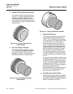
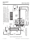
A-11 CELL REPLACEMENT
This paragraph covers oxygen sensing cell re-
placement. Do not attempt to replace the cell
until all other possibilities for poor performance
have been considered. If cell replacement is
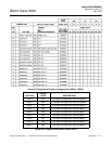
needed, order cell replacement kit, Table A-3.
The cell replacement kit contains a cell and
flange assembly, corrugated seal, setscrews,
socket head cap screws, and anti-seize com-
pound. Items are carefully packaged to preserve
precise surface finishes. Do not remove items
from packaging until they are ready to be used.
Spanner wrenches and hex wrenches needed for
this procedure are part of an available special
tools kit, Table A-3.
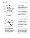
Wear heat resistant gloves and cloth-
ing to remove probe from stack. Nor-
mal operating temperatures of diffusor
and vee deflector are approximately
600° to 800°F (316° to 427°C). They
could cause severe burns.
Disconnect and lock out power before
working on any electrical components.
There is voltage up to 115 Vac.
Do not remove cell unless it is certain
that replacement is needed. Removal
may damage cell and platinum pad. Go
through complete troubleshooting
procedure to make sure cell needs re-
placement before removing it.
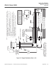
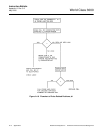
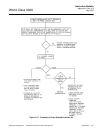
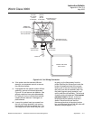
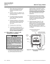
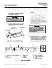
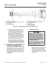
a. Disconnect and lock out power to electron-
ics. Shut off and disconnect reference air
and calibration gas supplies from probe
junction box, Figure A-18. Wearing heat re-
sistant gloves and clothing, remove probe
assembly from stack carefully and allow to
cool to room temperature. Do not attempt to
work on unit until it has cooled to a comfort-
able working temperature.