


Instruction Bulletin
Appendix A Rev. 3.9
May 2005
Rosemount Analytical Inc. A Division of Emerson Process Management Appendices A-5
World Class 3000
CALIBRATION
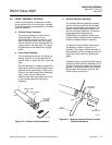
GAS FITTING
PROBE
JUNCTIONBOX
COVER
TERMINAL
STRIP
REFERENCE
AIR FITTING
27270016
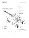
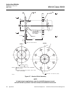
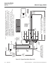
Figure A-6. Probe Junction Box
A-4 PROBE JUNCTION BOX
The probe junction box, Figure A-6, is
positioned at the external end of the probe and
contains a terminal strip for electrical
connections and fittings for reference air and
calibration gases. Fittings are for 0.250 inch
stainless steel tubing on American units and
6 mm on European units. The calibration fitting
has a seal cap which must remain in place
except during calibration. A tubing fitting is also
supplied to be used with the calibration gas
supply during calibration.
If the calibration gas bottles will be permanently
hooked up to the probe, a manual block valve is
required at the probe (between the calibration
fitting and the gas line) to prevent condensation
of flue gas down the calibration gas line.
During operation and calibration, reference air is
supplied through the reference air fitting to the
reference side of the cell. This gives the system
a known quantity of oxygen with which to
compare the oxygen level in the process gas.
Though ambient air can be used for this
purpose, accuracy can only be assured if a
reference air set is used.
During calibration, two gases of different known
oxygen concentrations are injected one at a
time through the calibration gas fitting. Stainless
steel tubing delivers this gas to the process side
of the cell. In a healthy cell, the difference in
oxygen pressure from the process side to the
reference side of the cell will cause a millivolt
output proportional to the difference in oxygen
levels. The electronics unit can use the two
millivolt outputs caused by the two calibration
gases for either automatic or semi-automatic
calibration.
Do not attempt to remove a process
gas sample through either gas fitting.
Hot gases from the process would
damage gas hoses in the probe
junction box.
A-5 CABLE ASSEMBLY
The system uses a 7-conductor cable to
connect the probe to the electronics package.
Standard length for this cable is 20 feet (6 m),
but lengths up to 150 feet (45 m) are available.
The seven conductors include one shielded pair
of wires for the cell millivolt signal, one shielded
pair of type K wires for the thermocouple, and
three individual 16-gauge wires for the heater
and for ground. The assembled conductors are
wrapped by a type K Teflon
TM
jacket and
braided stainless steel shield. The Teflon
TM
and
stainless steel jacketing is suitable for high
temperature use. All metal shields are isolated
at the probe end and connect by drain wires to
ground at the electronics.
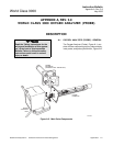
A-6 PROBE OPTIONS
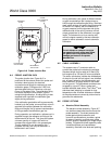
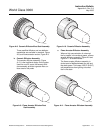
a. Abrasive Shield Assembly
The abrasive shield assembly, Figure A-7,
is a stainless-steel tube that surrounds the
probe assembly. The shield protects the
probe against particle abrasion and
corrosive condensations, provides a guide
for ease of insertion, and acts as a probe
position support, especially for longer length
probes. The abrasive shield assembly uses
a modified diffusor and vee deflector
assembly, fitted with dual dust seal packing.