


Instruction Bulletin
Appendix B Rev. 2.3
May 2005
Rosemount Analytical Inc. A Division of Emerson Process Management Appendices B-3
World Class 3000
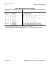
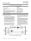
Table B-1. Specifications for Heater Power Supply
Environmental Classification.................................................. NEMA 4X (IP56) Optional - Class 1, Division 1,
Group B (IP56)
Electrical Classification ......................................................... Category II
Humidity Range ..................................................................... 95% Relative Humidity
Ambient Temperature Range ................................................ -20° to 140°F (-30° to 60°C)
Vibration ................................................................................ 5 m/sec
2
, 10 to 500 xyz plane
Cabling Distance Between HPS 3000 and Probe.................. Maximum 150 feet (45 m)
Cabling Distance Between HPS 3000 and CRE 3000........... Maximum 1200 feet (364 m)
Cabling Distance Between HPS 3000 and IFT 3000 ............ Maximum 1200 feet (364 m)
Approximate Shipping Weight................................................ 12 pounds (5.4 kg)
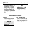
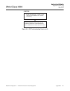
B-2 THEORY OF OPERATION
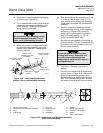
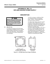
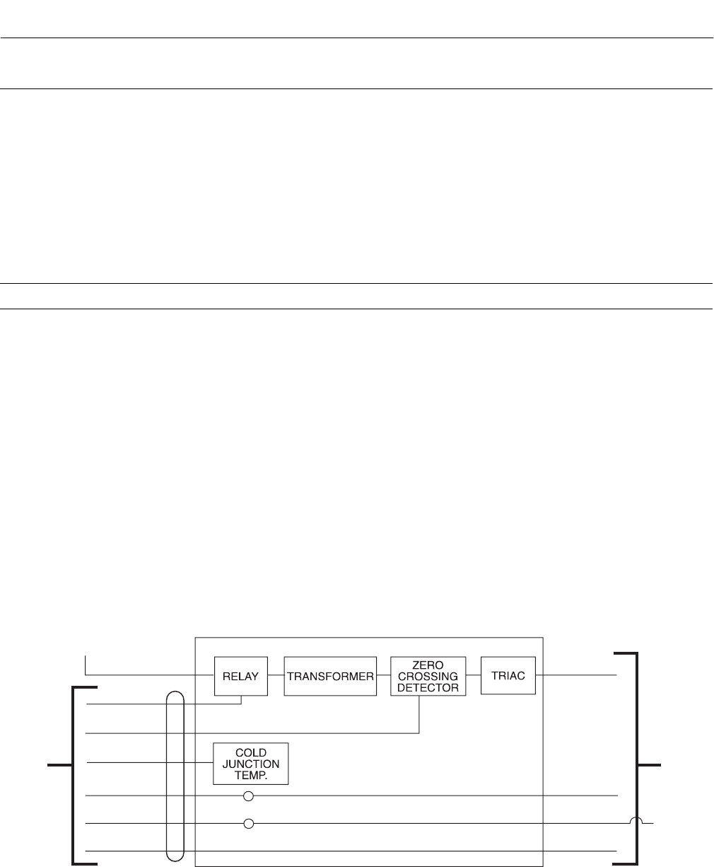
The HPS 3000 Heater Power Supply may per-
form slightly different functions, depending upon
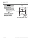
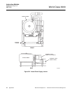
which electronics package it is used with. Figure
B-3 shows a functional block diagram of the
unit. The HPS contains a transformer for con-
verting line voltage to 44 volts needed to power
the probe heater. The relay, Figure B-3, can be
used to remotely turn the probe on or off manu-
ally. A triac module is used to turn the heater on
or off, depending on probe temperature.
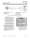
When used with the CRE 3000 Control Room
Electronics or IFT 3000 Intelligent Field Trans-
mitter, the HPS uses a cold junction tempera-
ture compensation feature. This allows for the
use of a less expensive cable between the HPS
and CRE or HPS and IFT. The HPS and elec-
tronics package can be located up to 1200 feet
(364 m) apart.
The standard cable, between probe and HPS, is
thermocouple compensated. This prevents the
additional junctions between thermocouple and
cable from producing a voltage which would af-
fect the thermocouple output signal. A tem-
perature sensor in the HPS monitors the
temperature at the junction and sends a voltage
signal to the CRE and IFT. The CRE and IFT
uses this signal to compensate the probe ther-
mocouple reading for the temperature at the
junction between the compensated and uncom-
pensated cables.
TO HEATER
PROBE TC
STACK TC
CELL
LINE
RELAY
TRIAC
AD590
PROBE TC
STACK TC
CELL MV
FROM
IFT
TO
PROBE
686015
Figure B-3. Heater Power Supply Block Diagram