


Instruction Manual
IB-106-300NH Rev. 4.3
May 2005
Rosemount Analytical Inc. A Division of Emerson Process Management Installation 2-21
World Class 3000
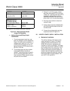
2-4 MULTIPROBE CALIBRATION GAS
SEQUENCER INSTALLATION
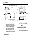
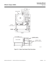
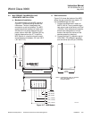
a. Mechanical Installation
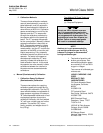
The outline drawing of the MPS module in
Figure 2-17 shows mounting centers and
clearances. The box is designed to be
mounted on a wall or bulkhead. The MPS
module should be installed no further than
300 feet (91 mz) piping distance from the
probe, and no more than 1000 feet (303 m)
cabling distance from the IFT. Install the
MPS module in a location where the ambi-
ent temperature is between -20° and 160°F
(-30° and 71°C).
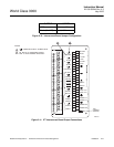
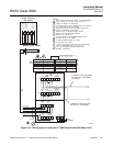
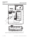
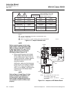
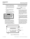
b. Gas Connections
Figure 2-18 shows the bottom of the MPS
where the gas connections are made. 1/4
inch threaded fittings are used.
1. Connect the reference air supply to
INSTR. AIR IN. The air pressure regu-
lator valve is set at the factory to 20 psi
(138 kPa). If the reference air pressure
should need readjustment, turn the
knob on the top of the valve until the
desired pressure is obtained.
2. Connect the high O
2
calibration gas to
HIGH GAS. The calibration gas pres-
sure should be set at 20 psi (138 kPa).
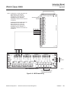
HIGH CAL
GAS IN
LOW CAL
GAS IN
CAL GAS
OUT
REF AIR
OUT
INSTR
AIR
REF AIR
OUT
REF AIR
OUT
REF AIR
OUT
CAL GAS
OUT
CAL GAS
OUT
CAL GAS
OUT
PROBE 1 PROBE 2 PROBE3 PROBE4
0.84 (21.34)
37840010
1.96 (49.78)
4.21 (106.93)
3.09 (78.49)
5.25 (133.35)
5.54 (140.72)
14.00 (355.60) REF
12.00
(304.80)
12.00
(304.80)
10.00
(254.00)
NOTE: DIMENSIONS ARE IN INCHES
WITH MILLIMETERS IN
PARENTHESES.
Analytical
Figure 2-17. MPS Module