


Instruction Bulletin
Appendix D Rev. 2.5
May 2005
D-10 Appendices Rosemount Analytical Inc. A Division of Emerson Process Management
World Class 3000
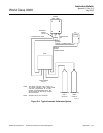
D-10 FLOWMETER ADJUSTMENTS
There are two flowmeters per flowmeter assem-
bly. The top flowmeter is factory set to 5 scfh.
The bottom flowmeter is set to 2 scfh. Should
the flow need to be changed or adjusted, use
knob on the bottom of the respective flowmeter.
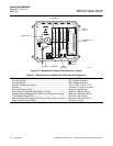
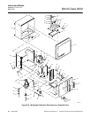
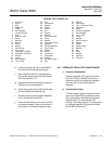
D-11 ADDING PROBES TO THE MPS
This procedure is used to add a probe to the
MPS.
Disconnect and lock out power before
working on any electrical components.
a. Turn off power to the system.
b. Loosen the two captive screws holding the
MPS cover (15). Lift the cover.
c. Loosen the two captive screws that hold the
inner cover (16) and lower the cover.
d. From the backside of the inner cover, locate
the flowmeter positions next to the existing
unit(s). Insert a hacksaw blade into the slots
surrounding the positions for two flowme-
ters, and saw out the knockout tabs.
e. From the front of the inner cover, install a
flowmeter (P/N 771B635H01) into the top
hole and a flowmeter (P/N 771B635H02)
into the bottom hole. From the backside se-
cure with brackets provided.
f. Remove four brass screw plugs (CAL GAS
IN, CAL GAS OUT, REF AIR IN, and REF
AIR OUT) for the next probe position in the
manifold.
g. Install 1/8" hose adapters (P/N
1A97553H01) into the empty holes using a
suitable pipe dope. Attach the tubing.
h. Remove a brass screw plug (P/N
1A97900H01) and install a solenoid (P/N
3D39435G01). Make sure the O-ring seals
properly.
i. Attach the hoses to the flowmeter using the
existing installation as a guide. Support the
flowmeter while attaching the hose.
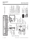
j. Install the solenoid wire connector into the
proper position (J14-J16) on the termination
board (34).
k. Close and secure the inner cover (16) with
two captive screws. Close and secure the
outer cover (15) with two captive screws.