


Instruction Manual
IB-106-300NH Rev. 4.3
May 2005
Rosemount Analytical Inc. A Division of Emerson Process Management Installation 2-13
World Class 3000
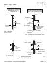
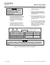
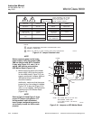
OUTPUT JUMPER
HPS Remove JM6
Probe (No HPS) Install JM6
ANALOG OUTPUT
(Condition during
microcontroller failure) Switch SW3
Output = zero SW3 on
Output = maximum SW3 off
(See Figure 2-9 for jumper and switch locations.)
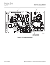
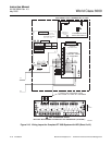
Figure 2-8. Microprocessor Board
Jumper Configuration
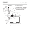
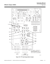
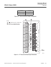
c. Analog Output and Relay Output
Connections
1. The microprocessor board has a se-
lector for voltage or current operations.
Figure 2-9 shows switch orientation. In
voltage mode, output is 0-10 V. In the
current mode, the output can be con-
figured from the SETUP menu to be 0-
20 mA or 4-20 mA.
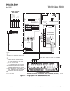
2. The analog output and relay outputs
are programmed by the user as
needed. The analog output is typically
sent to recording equipment such as
chart recorders. Relay outputs are typi-
cally sent to annunciators.
3. Relays K1 and K2 are user configur-
able from the probe SETUP sub-menu
(Table 5-5). Typically these are used to
indicate O
2
values above or below
specified tolerances. OK relay is ener-
gized when unit is functioning properly.
4. All wiring must conform to local and
national codes.
5. Analog output requires shielded cable
with the shield terminated at the inter-
connect board.
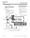
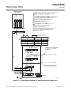
6. Connect the analog output and relay
outputs as shown in Figure 2-11.
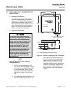
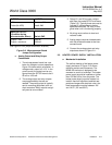
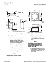
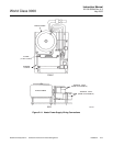
2-3 HEATER POWER SUPPLY INSTALLATION
a. Mechanical Installation
The outline drawing of the heater power
supply enclosure in Figure 2-12 shows
mounting centers and clearances. The
NEMA 4X enclosure is designed to be
mounted on a wall or bulkhead. The heater
power supply should be installed no further
than 150 feet (45 m) from the probe. The
heater power supply must be located in a
location free from significant ambient tem-
perature changes and electrical noise. Am-
bient temperature must be between -20°
and 140°F (-30° and 60°C).