


Instruction Manual
IB-106-300NH Rev. 4.3
May 2005
Rosemount Analytical Inc. A Division of Emerson Process Management General User Interface (GUI) Operation 5-3
World Class 3000
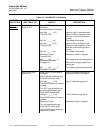
Table 5-1. Sample HELP Messages
MENU, SUB-MENU, HELP
OR PARAMETER NAME MESSAGE
PROBE DATA Press ENTER key to access DATA menu.
CALIBRATE O
2
The CAL menu is used to start calibration and view calibration.
SETUP The SETUP menu is used to configure the IFT 3000.
5-3 HELP KEY
The HELP key will display explanatory informa-
tion about a menu, sub-menu, or parameter that
the asterisk is next to when pressed. The HELP
key is not available during calibration routines.
Refer to Table 4-1 for sample HELP messages.
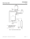
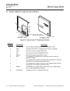
5-4 STATUS LINE
The top line of the LCD display (1, Figure 5-1) is
a status line that always displays system status,
menu name, and O
2
level. System status dis-
plays will be displayed one at a time in priority
sequence, as follows:
a. Off - The probe has been turned off be-
cause the IFT cannot control the heater
temperature.
b. PrbEr - The probe is disconnected, cold, or
leads are reversed.
c. HtrEr - Heater error.
d. InCAL - Calibration in progress.
e. Low O
2
- O
2
value is below the low alarm
limit.
f. HiO2 - O
2
value is above the high alarm
limit.
g. NoGas - Calibration gas pressure is low.
h. CalEr - Calibration error.
i. ResHi - Resistance is above the high limit.
j. OK - System is functioning correctly.
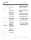
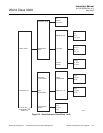
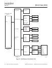
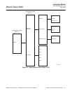
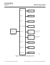
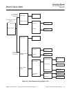
5-5 QUICK REFERENCE CHART
The quick reference chart (Figure 5-2) is de-
signed to help you get where you want to be in
the menu system. The chart shows all the avail-
able menu and sub-menu options for the IFT.
Follow the lines to determine which menu
choices to make. Moving down a level on the
chart is accomplished by the use of the ENTER
key. To move up a level on the chart, press the
ESCAPE key.
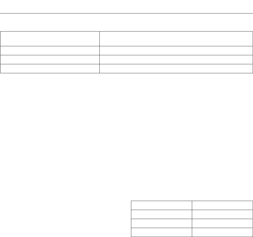
5-6 MAIN MENU
When power is first applied to the IFT, the MAIN
menu (Table 5-2) is initially displayed. It is from
the MAIN menu that the PROBE DATA (Table
5-3), CALIBRATE O
2
(Table 5-4), and SETUP
(Table 5-5) menus can be accessed.
Table 5-2. MAIN menu
MENU SELECTION DESCRIPTION
PROBE DATA Refer to Table 5-3.
CALIBRATE O
2
Refer to Table 5-4.
SETUP Refer to Table 5-5.
5-7 PROBE DATA SUB-MENU
The PROBE DATA sub-menu is a list of all the
parameters of the system as it is currently
configured. To access the PROBE DATA
sub-menu, press the DATA key at any time. The
increase and decrease keys are used to scroll
through the list. The PROBE DATA sub-menu
can be viewed but not changed. The operator
must use the SETUP menu to change any of
the parameters.
There are two selections available on the
PROBE DATA sub-menu; Process Data and
Diagnostic Data. Refer to Table 5-3 for contents
of the sub-menu.