


Instruction Bulletin
Appendix B Rev. 2.3
May 2005
B-8 Appendices Rosemount Analytical Inc. A Division of Emerson Process Management
World Class 3000
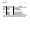
SERVICE AND NORMAL MAINTENANCE
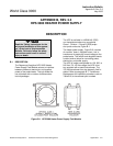
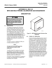
B-5 OVERVIEW
This section describes service and routine
maintenance of the HPS 3000 Heater Power
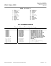
Supply Field Module. Replacement parts
referred to are available from Rosemount
Analytical. Refer to Table B-2 of this manual
for part numbers and ordering information.
Install all protective equipment covers
and safety ground leads after equip-
ment repair or service. Failure to in-
stall covers and ground leads could
result in serious injury or death.
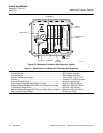
B-6 FUSE REPLACEMENT
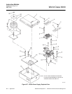
The heater power supply mother board (12,
Figure B-7) contains four identical 5 amp fuses.
Refer to Table B-1 for replacement fuse specifi-
cations. To check or replace a fuse, simply un-
screw the top of the fuseholder with a flat head
screwdriver and remove fuse. After checking or
replacing a fuse, reinstall fuseholder top.
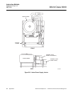
B-7 TRANSFORMER REPLACEMENT
Install all protective equipment covers
and safety ground leads after equip-
ment repair or service. Failure to in-
stall covers and ground leads could
result in serious injury or death.
a. Turn off power to system.
b. Loosen captive screws retaining HPS cover.
Remove cover.
c. Remove hex nut (25, Figure B-7) from top of
transformer assembly. Remove retaining
plate (24) and gasket (22).
d. Disconnect transformer harness plug from
mother board.
e. Remove old transformer. Place new trans-
former in position and reconnect harness
plug as noted in step d.
f. Place gasket and retaining plate on trans-
former.
g. Tighten hex nut only enough to firmly hold
transformer in place.
h. Reinstall HPS cover.
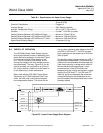
B-8 MOTHER BOARD REPLACEMENT
Install all protective equipment covers
and safety ground leads after equip-
ment repair or service. Failure to in-
stall covers and ground leads could
result in serious injury or death.
a. Turn off power to system.
b. Loosen captive screws retaining HPS cover.
Remove cover.
c. Remove hex nut (25, Figure B-7) from top of
transformer assembly. Remove retaining
plate (24) and gasket (22).
d. Disconnect transformer harness plug from
mother board.
e. Remove screws on either side of terminal
strip covers (2). Remove terminal strip cov-
ers (4 and 8).
f. Unplug ribbon cable from the receptacle on
the daughter board (7).
g. Unscrew stand offs on either side of the
daughter board. Remove daughter board
(7).
h. Unscrew four stand offs that supported the
daughter board.